RAD-...-IFS
96 / 198
PHOENIX CONTACT 105542_en_05
7.2.4 Basic circuit diagram
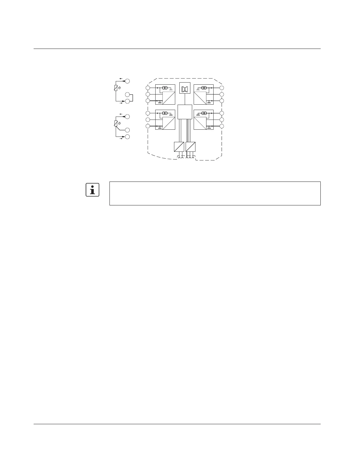
Figure 7-12 Basic circuit diagram for the RAD-PT100-4-IFS
For 2-wire connection technology, an insertion bridge is required between terminal blocks
x.2 and x.3. In this case, the measuring accuracy is reduced (see “Measuring errors when
using 2-wire connection technology” on page 93).
2.1
2.3
+I
1
-I
1
3-wire
2.2
-U
1
µC
2.1
2.2
2.3
3.1
3.2
3.3
5.1
5.2
5.3
4.1
4.2
4.3
IO-MAP
0
1
DC
DC
IFS
IFS
A
D
1mA
A
D
1mA
A
D
1mA
A
D
1mA
-I2
-U2
+I2
+I1
-U1
-I1
+I3
-U3
-I3
+I4
-U4
-I4
2.1
2.3
+I
1
-I
1
2.2
+I
1
2-wire

 Loading...

