BALANCING
1. It is critical that your airplane be balanced correctly.
Improper balance will cause your plane to lose
control and crash.
THE CENTER OF GRAVITY IS LOCATED 85mm
BACK FROM THE LEADING EDGE OF THE
WING, AT THE FUSELAGE.
2. Mount the wing to the fuselage. Using a couple of
pieces of masking tape, place them on the top side
of the wing 85mm back from the leading edge, at
the fuselage sides.
3. Turn the airplane upside down. Place your fingers on
the masking tape and carefully lift the plane .
4. If the nose of the plane falls, the plane is nose
heavy. To correct this first move the battery pack
further back in the fuselage. If this is not possible or
does not correct it, stick small amounts of lead
weight on the fuselage under the horizontal
stabilizer. If the tail of the plane falls, the plane is tail
heavy. To correct this, move the battery and
receiver forward or if this is not possible, stick
weight into the firewall. When balanced correctly,
the airplane should sit level or slightly nose down
when you lift it up with your fingers.
CONTROL THROWS
1. We highly recommend setting up a plane using the
control throws listed.
2. The control throws should be measured at the widest
point of each control surface.
3. Check to be sure the control surfaces move in the
correct directions.
85mm
Elevator Control
Aileron Control
12mm
12mm
Rudder Control
20mm
20mm
12mm
12mm
1. Turn the airplane upside down. Attach one loop of
heavy string to the engine crankshaft and one to the
tail wheel wire. With the wings level, carefully lift
the airplane by the string. This may require two
people to make it easier.
2. If one side of the wing fall, that side is heavier than
the opposite. Add small amounts of lead weight to
the bottom side of the lighter wing half's wing tip.
Follow this procedure until the wing stays level
when you lift the airplane.
LATERAL BALANCE
After you have balanced a plane on the C.G. You
should laterally balance it. Doing this will help the
airplane track straighter
!!!
FLIGHT PREPARATION PRE FLIGHT CHECK
1. Completely charge your transmitter and receiver
batteries before your first day of flying.
2. Check every bolt and every glue joint in your plane
to ensure that everything is tight and well bonded.
3. Double check the balance of the airplane
4. Check the control surface
5. Check the receiver antenna . It should be fully
extended and not coiled up inside the fuselage.
6. Properly balance the propeller.
16
Aileron 12mm up 12mm down
Elevator 12mm up 12mm down
Rudder 20mm right 20mm left
Low rate:
100
Glue the belly pan fairing.
I/C FLIGHT GUIDELINES
Made in Vietnam
When ready to fly, first extend the
transmitter aerial.
Operate the control sticks on the
transmitter and check that the control
surfaces move freely and in the
CORRECT directions.
ALWAYS land the model INTO the
wind, this ensures that the model lands
at the slowest possible speed.
Switch on the transmitter.
Switch off the transmitter.
Check that the transmitter batteries
have adequate power.
Switch off the receiver.
Switch on the receiver.
ALWAYS take off into the wind.
Check that the wings are correctly
fitted to the fuselage.
If the model does not respond correctly
to the controls, land it as soon as
possible and correct the fault.
Empty the fuel tank after flying, fuel left
in the tank can cause corrosion and
lead to engine problems.
KIT CONTENTS: We have organized the parts as they come out of the box for better identification
during assembly. We recommend that you regroup the parts in the same manner. This will ensure you
have all of parts required before you begin assembly.
THROTTLE CONTROL SYSTEM
(1) Metal rod 1,2mm x 500mm
(1) Nylon housing 3,5mm x 350mm
(1) Metal connector
(1) 4mm x 4mm screw
FUEL TANK
(1) Fuel tank
(1) Metal clunk
(1) 110mm silicon tube
(1) Stopper
(1) 80mm x 120mm foam.
MISCELLANEOUS ITEMS
(1) Dihedral
(1) Spinner
(1) 25mm x 600mm trim tape
(4) Plastic screw
(2) Plastic plate
(4) 2,6mm x 10mm screw
(1) Decal sheet
(3) Metal rod 1,7mm x 900mm
(2) Plastic belly pan fairings
ELEVATOR CONTROL SYSTEM
(2) Metal clevis M2
(1) Nylon clasp
(2) Nylon control horn
(4) 2mm x 20mm screw
(1) Domino
(1) Metal rod.
RUDDER CONTROL system
(1) Metal clevis M2
(1) Nylon clasp
(1) Nylon control horn
(2) 2mm x 20mm screw
AILERON CONTROL SYSTEM
(2) Metal rod 1,7mm x 30mm
(2) Metal clevis M2
(2) Nylon clasp
(2) Nylon control horn
(4) 2mm x 20mm screw
(4) Hard wood block
(8) 2mm x 12mm screw
ENGINE MOUNT
(4) 3mm x 20mm screw
(4) 3mm lock washer
KIT CONTENTS
AIR FRAME ASSEMBLIES
(2) Wing halves with ailerons
(1) Fuselage with canopy.
(1) Horizontal stabilizer with elevator halves
(1) Vertical stabilizer with rudder
(1) Cowling
(1) Decal sheet
(1) Instruction manual
MAIN GEAR ASSEMBLY
(2) Main gear
(2) 60mm diameter wheels
(2) connector gear
(2) Metal rod 1.7mm x 30mm
(2) Metal clevises M2
(2) Metal connector
(2) Plastic cover
(8) 2mm x 10mm screws
TAIL GEAR ASSEMBLY
(1) Tail gear
(1) 25mm diameter wheel
(2) Wheel collar
(2) plastic clasp
(6) 2mm x 10mm screws
1
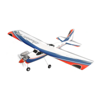
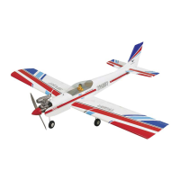
Wingspan : 1400 mm (55 inch)
Length : 1240 mm (48.8 inch)
Weight : 2800 g - 2900 g
Engine : 40 - 46 two stroke / 52 four stroke
Radio : 5 servo standard / 1 servo retract gear
g
Instruction Manual
Instruction Manual
2
1 2
3 4
5 6
7 8
Remove the covering from the top of the wing. Remove the covering from the aileron servo box.
Four blocks of hard wood. Glue the two hard wood by C.A glue.
Install the aileron servo. Connect the aileron servo to the 230mm servo extension
(not included in the kit).
Tape the servo lead into the end of the thread. Pull the servo lead out.
Installing the aileron servo and linkage.
1
15
93
94 95
96 97
98 99
Install the radio.
Prepare the belly pan fairings. Mark the belly pan fairing onto the wing.
Remove the covering. Glue the belly pan fairing.
Mark the belly pan fairing onto the wing. Remove the covering.
Switch
Receiver
Battery
Installing the belly pan fairings.
14
3
9 10
11 12
13
14
Using the masking tape, tape the servo lead onto the top of
the wing.
Secure the aileron servo box.
The control horn of the aileron. Mark two holes from the control horn onto the bottom of
the aileron and INLINE with the servo arm.
Secure the control horn.
Install the metal clevis to the aileron pushrod.
Control horn
Wrong
Wing Aileron
Wing Aileron
Control horn
Correct
Silicone tube
Nut
Metal clevis
4
15 16
17 18
19 20
21 22
Bend “L” and cut away the aileron pushrod. Attach the nylon clasp.
One set of the landing gear. Insert the landing gear into the block and mark four holes
onto the block.
Take out the landing gear and drill four holes into the block. Attach the metal rod to the landing gear.
Install and secure the landing gear into the block. Prepare the plastic part.
Nylon clasp
Metal clevis M2
Metal rod
Installing the landing gear.
2
5
23 24
25
26 27
28 29
Glue the plastic part by C.A glue and make a hole. Install the wheel into the connector of the gear.
Install the metal connector to the landing gear.
Draw a center line. Remove the covering.
Glue the wing joiner to the wing, using the epoxy glue. Apply the epoxy onto the wing section.
Cut away
Joining the wing halves.
3
Center line
6
30 31
32 33
34
35 36
Fix the wing and apply the trim tape to the center section
on the top of the wing where they join.
Apply the trim tape to the center section on the bottom of
the wing where they join.
Install the gear servo. Install two metal connector to the servo arm.
Install the servo arm and attach two rods to the metal
connector, secure the servo arm.
Make a center line onto the horizontal. Remove the covering from the rear of the fuselage.
Installing the landing gear servo.
4
Installing the horizontal stabilizer and vertical stabilizer.
5
Center line
7
37
38 39
40 41
42 43
Attach the horizontal to the fuselage and measure as photo
below.
Mark the shape of the fuselage onto the bottom of the
horizontal.
Cut away the covering.
Remove the covering from the bottom of the horizontal. Glue the horizontal and fuselage by epoxy.
Remove the covering from the rear of the vertical. Cut away the covering.
8
44 45
46 47
48 49
Attach the vertical to the fuselage and insert the hinge into
the slot.
Mark the shape of the vertical onto the top of the horizontal.
Remove the covering from the top of the vertical. Glue the vertical into the fuselage by epoxy and also glue the
hinge of rudder.
The tail gear. Make the slot onto the bottom of the rudder.
a1 a2
a1 = a2
Installing the tail gear.
6
9
50 51
52 53
54 55
56 57
Glue two nylon clasp by C.A glue into the rudder. Install the wheel and the collar into the tail gear.
Install the tail gear. Secure the tail gear.
The control horn of the elevator. Install the control horn onto the elevator.
Cut away the screw if necessary. Make the same way for the second elevator.
Installing the elevator pushrod and linkage.
7
Correct
Horizontal stabilizer Elevator
Control horn
Wrong
Control horn
Horizontal stabilizer Elevator
10
58
59 60
61 62
63 64
Remove the covering from both side of the fuselage.
Install the metal clevis to the elevator pushrod and insert the
pushrod into the fuselage (for both side).
Attach the metal clevis to the control horn of the left side of
elevator.
Attach the metal clevis to the control horn of the right side
of elevator.
Install the elevator servo into the fuselage.
Connect two elevator pushrod to the domino and secure
them.
Connect the domino to the servo arm and secure it by nylon
clasp.
Silicone tube
Nut
Metal clevis
Silicone tube
Silicone tube
Nylon clasp
11
65 66
67 68
69 70
71 72
The control horn of the rudder. Install the nylon control horn.
Cut away the screw if necessary. Remove the covering.
Install the metal clevis. Attach the metal clevis to the control horn.
Install the rudder servo into the fuselage. Connect the pushrod to the servo arm and secure it by
nylon clasp.
Installing the rudder pushrod and linkage.
8
Nylon clasp
Silicone tube
Nut
Metal clevis
12
73
74 75
76 77
78 79
Install the stopper to the tank.
Secure the stopper. Install the silicone tube of the tank.
Slide the fuel tank to the fuselage. Secure the fuel tank in place by rubber bank.
Drill a holes for throttle rod. Insert the plastic tube to the fuselage and secure it by
C.A glue.
Installing the fuel tank.
9
Installing the engine.
10
13
80 81
82 83
84
85 86
Attach the engine to the engine mount and mark four holes
(this picture use the 52 OS engine four stroke).
Drill four holes onto the engine mount.
Attach the throttle rod to the arm of the carburator. Install the engine and secure it.
Install the silicone exhaust (not included in the kit).
Install the throttle servo. Install the metal connector to the servo arm.
108 mm
Installing the throttle servo.
11
14
87
88 89
90
91 92
Attach the throttle rod into the metal connector and secure it.
Prepare the cowling. Install the cowling and secure it.
Install the propeller.
Cut away the wood. Install and secure the switch.
Screw
Cut
Installing the cowling, propeller.
12
Installing the switch.
13
41mm
230mm
Tape
Tape
120 mm