KIT CONTENTS: We have organized the parts as they come out of the box for better identification
during assembly. We recommend that you regroup the parts in the same manner. This will ensure you
have all of parts required before you begin assembly
AIR FRAME ASSEMBLIES
. (2) Wing halves with ailerons
. (1) Fuselage with canopy
. (1) Horizontal stabilizer with elevator halves
. (1) Vertical stabilizer with rudder
. (1) Cowling
. (1) Decal sheet
. (1) Instruction manual
MAIN GEAR ASSEMBLY
. (2) Main gear
. (2) 50mm diameter wheels
. (4) Wheel collars
. (4) Metal plate
. (8) 2mm x 10mm screws
NOSE GEAR ASSEMBLY
. (1) Nose gear
. (1) 50mm diameter wheel
. (2) Wheel collar
. (2) Metal plate
. (4) 2mm x 10mm screws
ELEVATOR CONTROL SYSTEM
. (1) Control horn
. (1) Wire metal rod (500mm)
. (1) Conector
. (1) 4 x 4mm screw
RUDDER CONTROL SYSTEM
. (1) Control horn
. (1) Wire metal rod (500mm)
. (1) Conector
. (1) 4 x 4mm screw
AILERON CONTROL SYSTEM
. (2) Metal rod (200mm)
. (2) 4 x 4mm screw
. (2) Control horn
. (2) Control horn
MOTOR MOUNT ASSEMBLY
. (1) Engine mount
. (4) 3mm x 10mm screws
. (4) Washer
MISCELLANEOUS ITEMS
. (1) Dihedral
. (2) 25mm x 300mm trim tape
. (4) 3mm x 25mm screws
. (2) Washer
. (4) 2mm x 10mm screws
. (1) Antena
. (1) Cowling
. (1) Decal sheet
KIT CONTENTS
Instruction Manual
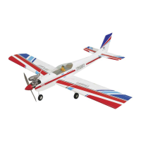
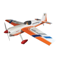
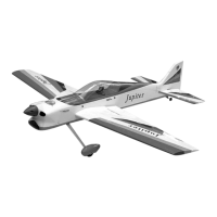
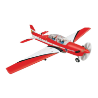
We wish you many enjoyable flights with your plane and once again thank you for your choosing a Phoenix Model product
Wing span: 945mm (37.2 in)
Length: 770mm (30.31 in)
Weight: 550gr - 620gr
Motor: AXI 2208 /26 or 400-500 w/ gear box
Radio: 4 channel/ 3 servos mini
g
Made in Vietnam
1
1 2
3 4
5 6
7 8
Remove the covering from the top of the wing. Remove the covering from the bottom of the wing.
Prepare the thread as a guide. Pull the servo lead out.
Using masking tape, tape the servo leads on the top of the
wing.
Install the servo into the servo box.
Install the connector into the servo arm. Test fit the dihedral brace into the box of the wing joiner.
2
9 10
11 12
13 14
15 16
Glue the wing with epoxy. Apply the trim tape to the center section of the wings where
they join.
Glue the aileron hinge by C.A. glue. Glue the control horn into the aileron by C.A. glue.
Install the metal rod into the aileron servo. Cut the metal rod.
Drill holes for landing gear. Install the landing gear.
3
17 18
19 20
21 22
23 24
Install the wheel collar. Install the wheel and the wheel collar.
Make the same way for the second wing. Glue the elevator hinge by C.A. glue.
Make the center line into the elevator. Insert the elevator into the slot of the fuselage.
Mark the shape of the fuselage on the top and on the bottom
of the elevator.
Cut away the covering from the top and the bottom of the
elevator.
4
25 26
27 28
29 30
31 32
Glue the elevator by epoxy.
Glue the rudder hinge by C.A. glue. Remove the covering from the fuselage.
Glue the rudder into the fuselage by epoxy.
Remove the covering from the exit slot for rudder. Insert the wire pushrod and also insert the control horn into
the wire pushrod.
BALANCING
1. It is critical that your airplane be balanced correctly.
Improper balance will cause your plane to lose
control and crash.
THE CENTER OF GRAVITY IS LOCATED 60mm
BACK FROM THE LEADING EDGE OF THE
WING, AT THE FUSELAGE.
2. Mount the wing to the fuselage. Using a couple of
pieces of masking tape, place them on the top side
of the wing 60mm back from the leading edge, at
the fuselage sides.
3. Turn the airplane upside down. Place your fingers on
the masking tape and carefully lift the plane .
4. If the nose of the plane falls, the plane is nose heavy.
To correct this first move the battery pack further
back in the fuselage. If this is not possible or does
not correct it, stick small amounts of lead weight on
the fuselage under the horizontal stabilizer. If the
tail of the plane falls, the plane is tail heavy. To
correct this, move the battery and receiver forward
or if this is not possible, stick weight into the
firewall. When balanced correctly, the airplane
should sit level or slightly nose down when you lift
it up with your fingers.
LATERAL BALANCE
After you have balanced a plane on the C.G. You
should laterally balance it. Doing this will help the
airplane track straighter
CONTROL THROWS
1. We highly recommend setting up a plane using the
control throws listed.
2. The control throws should be measured at the widest
point of each control surface.
3. Check to be sure the control surfaces move in the
correct directions.
1. Turn the airplane upside down. Attach one loop of
heavy string to the engine crankshaft and one to the
tail wheel wire. With the wings level, carefully lift
the airplane by the string. This may require two
people to make it easier.
2. If one side of the wing fall, that side is heavier than
the opposite. Add small amounts of lead weight to
the bottom side of the lighter wing half's wing tip.
Follow this procedure until the wing stays level
when you lift the airplane.
60 mm
!!!
Ailerons : 10mm up 10mm down
Elevator : 10mm up 10mm down
Rudder : 15mm right 15mm left
Elevator Control
Aileron Control
10mm
10mm
Rudder Control
15mm
15mm
10mm
10mm
FLIGHT PREPARATION PRE FLIGHT CHECK
1. Completely charge your transmitter and receiver
batteries before your first day of flying.
2. Check every bolt and every glue joint in your plane
to ensure that everything is tight and well bonded.
3. Double check the balance of the airplane
4. Check the control surface
5. Check the receiver antenna . It should be fully
extended and not coiled up inside the fuselage.
6. Properly balance the propeller.
We wish you many enjoyable flights with your
plane and once again thank you for your choosing
a Phoenix Model product
5
33 34
35 36
37 38
39 40
Cut away the wood from the rudder. Glue the control horn by C.A. glue.
Remove the covering from the exit slot for elevator. Insert the wise pushrod and also insert the control horn into
the wire pushrod.
Cut away the wood from the elevator. Glue the control horn by C.A. hinge.
Install the rudder servo and elevator servo. Install the connector into the servo arm and secure the wire
pushrod.
6
41 42
43 44
45 46
47 48
Install the elevator, rudder pushrod into the servo. Glue the pushrod holder into the fuselage.
Prepare the engine mount. Glue the engine mount into the fuselage.
Drill four holes into the engine mount. The engine has been drilled.
Install the motor. Install the nose gear.
7
49 50
51 52
53 54
55 56
Install the wheel collar. Install the wheel and the wheel collar.
Make the hole for the cowling. Make the hole for the cowling.
Make the hole for the cowling. Cut away the cowling.
Install the cowling. Secure the cowling.
8
57
Install the propeller.