Do you have a question about the Phonic AM 2421X and is the answer not in the manual?
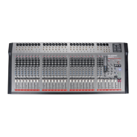
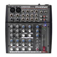
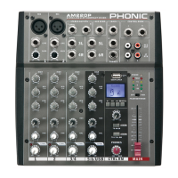
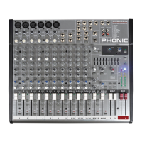
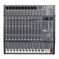
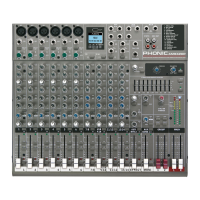
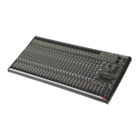
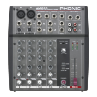
Lists key attributes of the AM mixing consoles, including audio quality, channel types, EQ, and connectivity.
Step-by-step guide to initially powering on and connecting the mixer, ensuring safe operation.
Procedure for setting individual input channel levels and gain to achieve optimal audio signal.
Details the various input and output connectors on the mixer's front panel for different audio sources.
Port for connecting a footswitch to remotely control built-in digital effects, allowing mute/unmute functionality.
1/4" phone jack outputs for feeding mixer signal to active monitors or for booth monitoring.
XLR and 1/4" TS output for monaural signal, suitable for mono systems or subwoofers.
XLR and 1/4" phone jacks providing the final stereo line level signal to external devices.
XLR socket for attaching a 12 Volt gooseneck lamp to improve visibility in low light conditions.
Connects the AC power cable and houses the fuse for the mixer's power supply.
RCA and mini stereo inputs for tape decks, CD players, and MP3 players to the Tape In mixing bus.
RCA and mini stereo ports for sending mixed audio to recording devices.
Output port for monitoring the mix using headphones, controlled by the master section.
High-pass filter that reduces frequencies below 75 Hz at 18 dB/octave to remove unwanted noise.
Attenuates the input signal by 20 dB for greater dynamic range on high-level inputs.
Adjusts the sensitivity of the input signal for Line/Microphone inputs to optimize audio levels.
Provides shelving boost/cut of +/-15 dB at 12 kHz to adjust treble and crispness in the audio.
Peaking boost/cut of +/-15 dB with a sweepable frequency between 100 Hz and 8 kHz.
Provides shelving boost/cut of +/-15 dB at 80 Hz to adjust bass and warmth.
Adjusts signal level sent to auxiliary 1 and 2 mixing buses for stage monitors or external effects.
Controls the level of audio sent to EFX 1 and 2 mixing buses, with EFX 2 also feeding the built-in DSP.
Adjusts the audio level sent to the left and right sides of the main mix (pan/balance).
Mutes the channel, stopping all audio from being sent to the main and auxiliary buses.
LED illuminates at 6 dB before overload, indicating signal peaks for dynamic range management.
LED indicates when the input level reaches -20 dBu, showing a signal is received.
Pre-Fader Listen button sends channel signal to CTRL RM/PHONES mix for monitoring.
60 mm fader that alters the signal level sent from the channel to the Main L/R mixing bus.
Scrolls through and applies effects shown on the Digital Effect Display.
LED illuminates for high EFX signal peaks, 6 dB before overload, for dynamic range.
Adjusts the specific parameter of the digital effect applied to the audio feed.
Allows calculation of tap delay time by pushing the button twice to set the interval.
Adjust signal level from the Effects Engine to auxiliary 1 and 2 mixing buses.
Mutes the EFX channel, stopping processed signal from reaching the Main L/R mix.
Sends the Effects Engine signal to the CTRL RM/PHONES mix for tracking audio.
60mm fader that alters the signal level from the Effects Engine to the Main L/R mix.
Controls the signal level from the Tape In mixing bus to Control Room/Phones and Main L/R mixing buses.
Buttons to send the Tape In signal to the Control Room or Main mixes for monitoring or combination.
Adjust the signal level of the Tape In sent to the auxiliary 1 and 2 mixing buses.
Adjust pre-fader levels from Stereo Returns to AUX buses for effect-to-monitor sends.
Alter the signal level sent from Stereo Returns to the Main L/R mix.
Send Stereo Return signals to Control Room/Phones mix (pre-fader, post-EQ) for monitoring.
60 mm faders alter signal level from AUX 1 and 2 to their corresponding outputs.
Activates +48V Phantom Power for microphone inputs, indicated by an illuminated LED.
Adjust final levels of EFX 1 and 2 signals sent to corresponding EFX sends.
60 mm faders control the final level for the Mono mixing bus, sent to the Mono/Subwoofer output.
12 segment meters indicate Main left/right audio signal levels and peak indicators.
Bi-colored indicator (green for PFL, red for AFL) showing signal priority in monitoring.
Details Phonic's warranty policy, duration, coverage, and requirements for service.
Provides contact information and resources for online support, FAQs, and technical assistance.
Lists available digital effect programs, their parameters, and variable ranges.
Illustrates common setup configurations for PA, live events, and church sound systems.
Provides physical dimensions (X and Y) for each model in millimeters and inches.
Presents a schematic overview of the mixer's internal signal flow and component connections.
| Type | Analog |
|---|---|
| Phantom Power | Yes |
| Outputs - Main | 2 x XLR |
| Faders | 60mm |
| Headphone Output | 1 x 1/4" |