“ASSEMBLE INSTRUCTIONS”
STEP 12 –
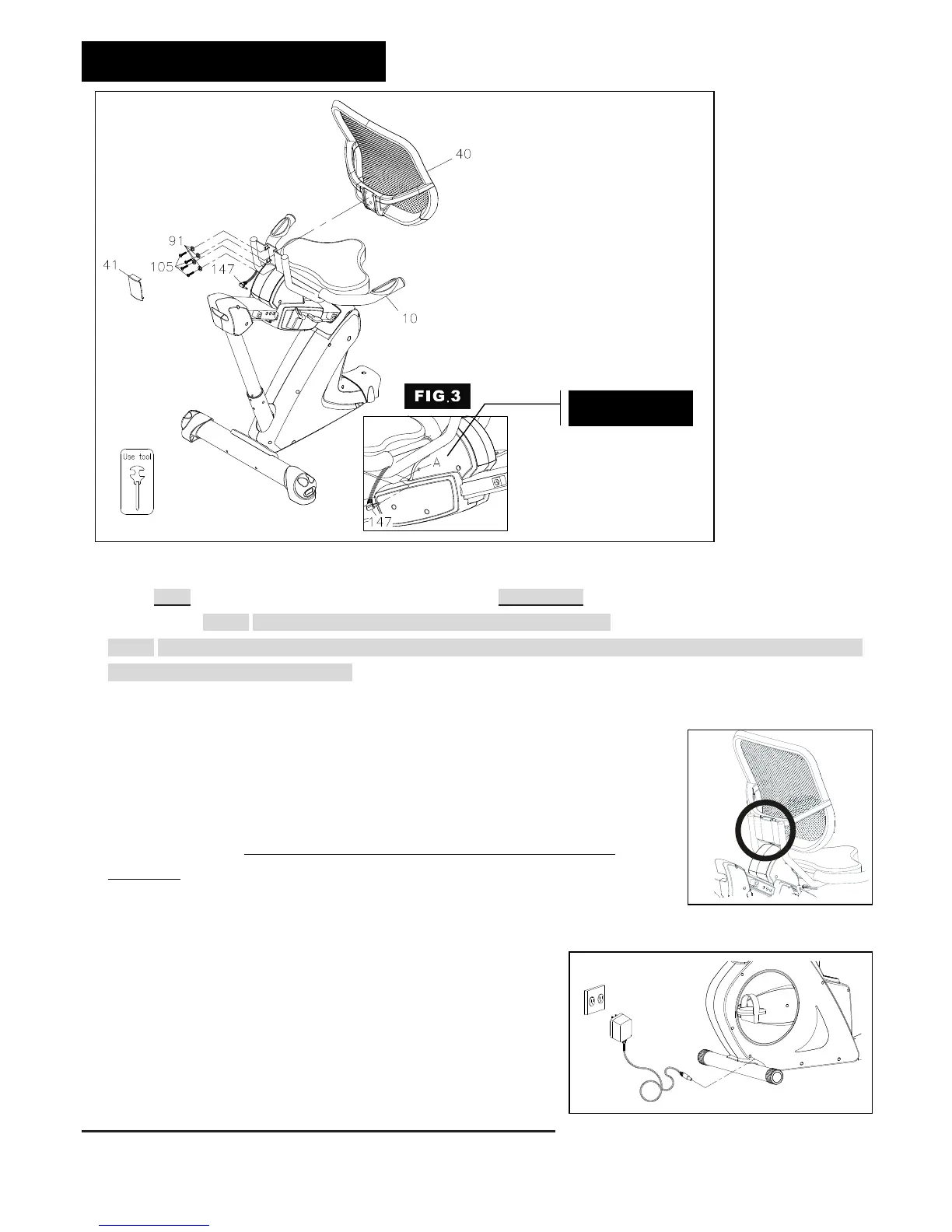
Pulse Sensor Wire and Mesh Backrest Assembly
a. Follow FIG.3 to plug the Pulse Sensor Wire 4 (147) into the connector A located on the left side of the Seat Carriage
Assembly (9) NOTE: Be careful not to pinch the Pulse Sensor Wire 4 (147).
b. NOTE: Four Screws, Round Head (1/4’’x20mm)(105) and Four Lock Washer (M6)(91) have been attached on the
back side of the Mesh Backrest (40).
c. Remove four Screws, Round Head (1/4’’x20mm)(105) and Four Lock Washer (M6)(91) from the back side of the
Mesh Backrest (40).
d. Attach the Mesh Backrest (40) to the Seat Frame (10) with four Lock Washer
(M6)(91)and four Screws, Round Head (1/4’’x20mm)(105).
e. Gently insert Mesh Backrest Cover (41) into the recesses located on the back of the
Seat Frame (10) as the right illustration shown.
f. Finish the assembly. Make sure that all parts are tightened before you use the
equipment.
STEP 13 –
AC Adaptor
a. Connect the Adaptor (148) to the connector located on the front left
side of the Main Frame (1).
b. Plug the Adaptor (148) into an electrical outlet to light up the
console.
 Loading...