ManualP6040 V30Page 7/12
Connections
Function Valve V30
a. Standard pump configuration 2x flap valves
b. Pump configuration with non-return valve
c. Limited vacuum level configuration 1x flap valve
Figure 1 Function valve V30.
Function ES vacuum
Figure 2 Pneumatic diagram.
A
D
A Switch mounted on vacuum sensing port
D Electrical connection
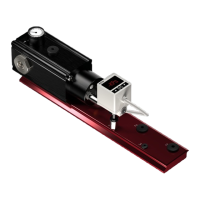
Function ES Blow
Figure 3 Pneumatic diagram.
D
E
E Switch mounted on blow sensing port
D Electrical connection
4. Connections
C
O.P
1
2
3
x3
B
2
3
1
2
3
3
2
B
C
O . P.
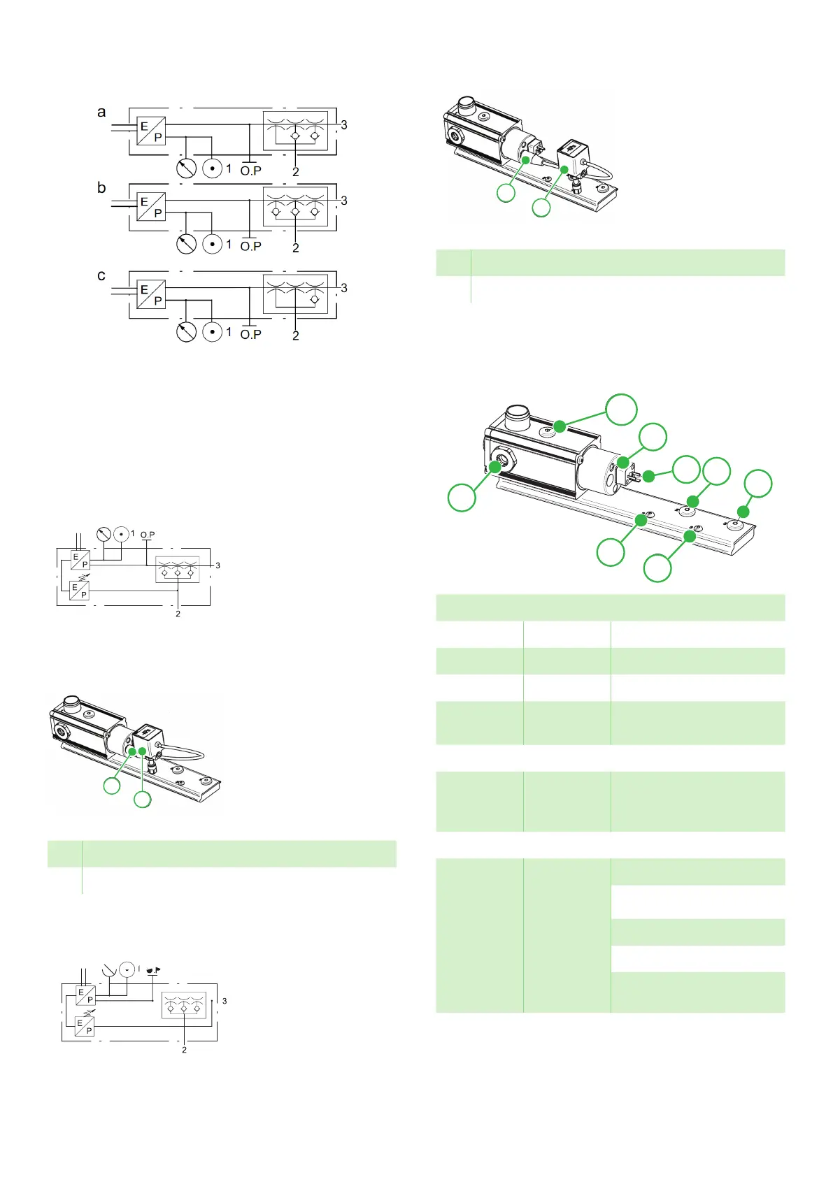
Pneumatic connections
1 G1/2” Compressed air port
2 M5/G1/8” Vacuum sensing port
3 M5/G1/8” Exhaust sensing port
O. P. G1/8” Operating pressure
sensing port
Indicators
B LED
Indicator
Status of air valve is
displayed by the LED
indicator
Electrical connections
C Connector
DIN43650
C-8 mm
Pin 1, 24 VDC On/Off
Pin 2, GND
D Connector
M8 3-pol,
vacuum/
pressure
switch
Pin 1, 24 VDC
Pin 4, Signal
Pin 3, GND