EasyManua.ls Logo

Pioneer A-307R - Service Manual

Pioneer A-307R
33 pages
Print Icon
To Next Page IconTo Next Page
Loading...
ORDER NO.
RRV1912
T - IZK APR. 1998 Printed in Japan
PIONEER ELECTRONIC CORPORATION 4-1, Meguro 1-Chome, Meguro-ku, Tokyo 153-8654, Japan
PIONEER ELECTRONICS SERVICE, INC. P.O. Box 1760, Long Beach, CA 90801-1760, U.S.A.
PIONEER ELECTRONIC (EUROPE) N.V. Haven 1087, Keetberglaan 1, 9120 Melsele, Belgium
PIONEER ELECTRONICS ASIACENTRE PTE. LTD. 501 Orchard Road, #10-00 Lane Crawford Place, Singapore 0923
PIONEER ELECTRONIC CORPORATION 1998
c
1. SAFETY INFORMATION ...................................... 2
2. EXPLODED VIEWS AND PARTS LIST ................ 3
3. SCHEMATIC DIAGRAM ....................................... 6
4. PCB CONNECTION DIAGRAM .......................... 14
5. PCB PARTS LIST ............................................... 22
6. ADJUSTMENT .................................................... 25
CONTENTS
7. GENERAL INFORMATION ................................ 26
7.1 IC ................................................................. 26
7.2 DISASSEMBLY ........................................... 27
7.3 BLOCK DIAGRAM....................................... 28
8. PANEL FACILITIES AND SPECIFICATIONS .... 29
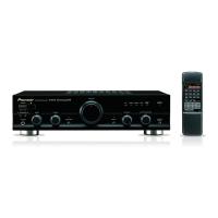
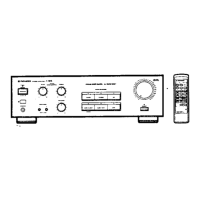
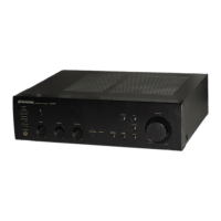
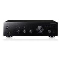
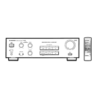
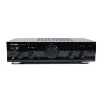
A-307R
STEREO AMPLIFIER
A-207R
THIS MANUAL IS APPLICABLE TO THE FOLLOWING MODEL(S) AND TYPE(S).
PH
A P A B
A P
D ec Ene gy MOS
AP
M
P
M
U
PH
BA
+
B
+
V UM
M MAX
U
BA A PU
AP
M
Type
Model
Power Requirement
A-307R A-207R
MYXJ/EW AC220-230V ––––
MYXJ/GR AC220-230V ––––
MVXJ AC220-230V ––––
SAMXJ AC110V/120-127V/220V/240V With the voltage selector
SDXJ AC110V/120-127V/220V/240V With the voltage selector
The voltage can be converted by the
following method.
The illustration shows the A-307R.

Other manuals for Pioneer A-307R

Questions and Answers

Pioneer A-307R Specifications

General IconGeneral
Speaker load impedance4 - 16 ohms
Frequency Response5Hz to 100kHz
Total Harmonic Distortion (THD)0.08%
Signal-to-Noise Ratio> 100 dB
Input Sensitivity150 mV
OutputSpeakers

Summary

SAFETY INFORMATION

SAFETY PRECAUTIONS

Precautions for continued protection of customer and technician.

PRODUCT SAFETY NOTICE

Importance of using specified replacement parts for safety.

EXPLODED VIEWS AND PARTS LIST

PACKING

Exploded view and parts list for product packing.

EXTERIOR

Exploded view of the external parts of the amplifier.

EXTERIOR PARTS LIST

List of external parts for different models.

CONTRAST TABLE

Comparison of parts across different models.

SCHEMATIC DIAGRAM

OVERALL CONNECTION DIAGRAM

Overall connection diagram showing main assemblies and interconnections.

VOLUME AND HEADPHONE ASSEMBLIES

Schematic diagram for volume and headphone assemblies.

AC PRIMARY ASSY

Schematic diagram for the AC primary assembly.

AF ASSY

Schematic diagram for the AF (Audio Frequency) assembly.

FRONT L, FRONT R AND OPT ASSEMBLIES

Schematic diagrams for front L, front R, and optical assemblies.

PCB CONNECTION DIAGRAM

VOLUME ASSY

PCB connection diagram for the volume assembly.

HEADPHONE AND AC PRIMARY ASSEMBLIES

PCB connection diagrams for headphone and AC primary assemblies.

AF ASSY

PCB connection diagram for the AF assembly.

FRONT L ASSY

PCB connection diagrams for the front L assembly.

FRONT R AND OPT ASSEMBLIES

PCB connection diagrams for front R and optical assemblies.

PCB PARTS LIST

WHOLE PCB ASSEMBLIES LIST

Comprehensive list of major PCB assemblies and their part numbers.

VOLUME ASSY PARTS LIST

Detailed list of semiconductor and capacitor parts for the volume assembly.

HEADPHONE ASSY PARTS LIST

Detailed list of parts for the headphone assembly.

AC PRIMARY ASSY PARTS LIST

Detailed list of parts for the AC Primary Assy.

AC PRIMARY ASSY CONTRAST TABLE

Contrast table for AC Primary Assy parts.

AWX7113 PARTS LIST

Specific parts list for the AWX7113 assembly.

DAF ASSY CONTRAST TABLE

Contrast table for DAF Assy parts across models.

AWX7119 PARTS LIST

Detailed parts list for the AWX7119 assembly.

ADJUSTMENT

IDLE CURRENT ADJUSTMENT

Procedure for adjusting idle current for amplifier stability.

GENERAL INFORMATION

IC: PD5443 A (REMOTE CONTROL AMP)

Pin assignment and function details for the PD5443A IC.

DISASSEMBLY

Step-by-step instructions for disassembling the unit.

BLOCK DIAGRAM

Block diagram illustrating the functional units of the amplifier.

PANEL FACILITIES AND SPECIFICATIONS

PANEL FACILITIES: REAR PANEL

Description and layout of the rear panel connections and ports.

PANEL FACILITIES: FRONT PANEL

Description and operation of front panel controls and indicators.

SPECIFICATIONS

Technical specifications for amplifier performance and power.

REMOTE CONTROL

REMOTE CONTROL FUNCTIONS

Explanation of buttons and their functions on the remote control unit.

Related product manuals