Do you have a question about the Pioneer AVH-280BT/XNUC and is the answer not in the manual?
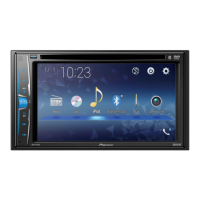
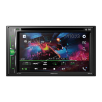
| Display Type | LCD |
|---|---|
| Screen Size | 6.2 inches |
| Resolution | 800 x 480 |
| DIN Size | Double DIN |
| Bluetooth | Yes |
| AUX Input | Yes |
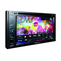
| DVD Player | No |
| Pandora Control | Yes |
| iPod/iPhone Control | Yes |
| Android Compatibility | Yes |
| Steering Wheel Control Compatible | Yes (Adapter required) |
| Camera Input | Yes |
| AM/FM Tuner | Yes |
| RMS Power Output | 14 watts |
| Peak Power Output | 50 watts x 4 |
| Audio Formats Supported | MP3, WMA |
| Video Formats Supported | MPEG-1, MPEG-2 |
| SiriusXM Ready | Yes |
Guidelines for qualified technicians on safe repair practices.
Conforming to regulations and following safety instructions.
Procedures and precautions for taking apart and reassembling the unit.
Guidelines for troubleshooting and verifying operations after repair.
Precautions for handling sensitive components and replacing parts.
Information on required adjustments after component replacement.
Details on soldering practices and environmental considerations.
General technical specifications of the AV receiver.
Supported disc types and content formats.
Essential checks to ensure product quality after repair.
Diagrams showing the physical placement of PCBs within the unit.
List of specialized tools and cleaning supplies for service.
Instructions for cleaning critical parts like pickup lenses.
A high-level overview of how major units and components connect.
Detailed block diagram of the main processing and control components.
Diagram illustrating the signal flow for audio and video processing.
Diagram showing power distribution and voltage levels across the system.
Step-by-step process for diagnosing power-on sequences.
Procedures for testing and diagnosing the optical pickup mechanism.
Table of error codes, meanings, sources, and reset methods.
Details on the purpose and pin assignments of external connectors.
How to view system software version and state.
Accessing and navigating the various diagnostic test modes.
Steps for updating the unit's internal software via USB.
Method to verify the installed firmware version of the unit.
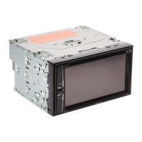
Steps for safely removing the display unit from the chassis.
Procedures for detaching the main circuit board of the display.
Steps for removing the button interface board.
Instructions for detaching the optical disc drive unit.
Steps for removing thermal management components.
Procedures for detaching chassis brackets and holders.
Steps for disconnecting and removing the main motherboard.
Specifies adjustments needed when major assemblies are replaced.
Steps to minimize screen flicker by adjusting values.
Diagram and list of items included in the product packaging.
Detailed list and diagrams of external cosmetic and structural parts.
Additional diagrams and parts list for exterior components.
Detailed list and diagrams of components within the DVD drive unit.
Further breakdown of parts for the DVD mechanism.
Circuit diagram for the sense circuitry on the mother unit.
Circuit diagram for the Bluetooth interface on the mother unit.
Circuit diagram for the USB power supply section of the mother unit.
Circuit diagram for the interface section of the mother unit.
Circuit diagram for the electronic volume control on the mother unit.
Circuit diagram for the DDC 2-channel control on the mother unit.
Circuit diagram for the FM/AM tuner section of the mother unit.
Circuit diagram for the power control (PWIC) on the mother unit.
Circuit diagram for the microcontroller (ucom) on the mother unit.
Circuit diagram for the power management circuits on the mother unit.
Circuit diagram for the System-on-Chip (SOC) on the mother unit.
Circuit diagram for the main interface of the monitor PCB.
Circuit diagram for the LCD backlight driver on the monitor PCB.
Circuit diagram for the LCD power control on the monitor PCB.
Circuit diagram for the LCD interface on the monitor PCB.
Circuit diagram for the Timing Control (TCON) on the monitor PCB.
Circuit diagram for the isolation components on the monitor PCB.
Circuit diagram for the relay control unit.
Circuit diagram for the button input interface board.
Visual representations of signal patterns for diagnostic purposes.
Diagrams showing how connectors interface with the mother unit PCB.
Diagrams illustrating connector assignments for the monitor PCB.
Diagrams showing connector interfaces for the relay unit PCB.
Diagrams detailing connector assignments for the key input PCB.
List of miscellaneous electronic parts used in the unit.