EasyManua.ls Logo

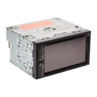
Pioneer AVH-285BT/XNRC User Manual

Pioneer AVH-285BT/XNRC
94 pages
To Next Page IconTo Next Page
Page #1 background imageLoading...
Page #1 background image
ORDER NO.
PIONEER CORPORATION 1-1, Shin-ogura, Saiwai-ku, Kawasaki-shi, Kanagawa 212-0031, Japan
PIONEER ELECTRONICS (USA) INC. P.O. Box 1760, Long Beach, CA 90801-1760, U.S.A.
PIONEER EUROPE NV Haven 1087, Keetberglaan 1, 9120 Melsele, Belgium
PIONEER ELECTRONICS ASIACENTRE PTE. LTD. 2 Jalan Kilang Barat, #07-01, Singapore 159346
PIONEER CORPORATION 2015
AVH-280BT/XNUC
CRT5859
DVD RDS AV RECEIVER
AVH-280BT/XNUC
AVH-280BT/XNEU5
AVH-285BT/XNRC
AVH-285BT/XNRD
AVH-285BT/XNRI
AVH-289BT/XNID
This service manual should be used together with the following manual(s):
Model No. Order No. Mech.Module Remarks
CX-3311 CRT5651 LS2.5 DVD Mech. Module : Circuit Descriptions, Mech. Descriptions, Disassembly,
Diagnosis , Each Setting and Adjustment
K-ZZZ DEC. 2015 Printed in Japan
Question and Answer IconNeed help?

Do you have a question about the Pioneer AVH-285BT/XNRC and is the answer not in the manual?

Pioneer AVH-285BT/XNRC Specifications

General IconGeneral
BrandPioneer
ModelAVH-285BT/XNRC
CategoryStereo Receiver
LanguageEnglish

Summary

SAFETY INFORMATION

Laser Safety Precautions

Crucial safety instructions regarding laser diode handling, distance, viewing, and radiation exposure.

SERVICE PRECAUTIONS

General Service Precautions

Conformity to product regulations and adherence to safety instructions during servicing.

Disassembly and Assembly Notes

Guidelines for safe disassembly, assembly, and laser diode protection during component replacement.

Operation Check and Diagnosis Notes

Notes on operation checks, diagnosis procedures, memory backup, and error handling.

Parts Replacement Notes

Precautions for handling ICs, electrostatic discharge, and replacement of specific module parts.

BASIC ITEMS FOR SERVICE

Post-Servicing Checkpoints

Essential checks to ensure product quality after service, covering playback and appearance.

BLOCK DIAGRAM

System Block Diagram

Detailed block diagram showing internal system components and their relationships.

Power Supply System Figure

Illustrates the power distribution, voltage levels, and current consumption of various components.

DIAGNOSIS

Operational Flowchart

Step-by-step flowchart detailing the power-on operational sequence.

Pickup Unit Inspection Method

Procedure for inspecting the pickup unit, including LD current, RF level, and error rate checks.

Error Code List

Table listing error codes, their meanings, sources, and methods for resetting them.

SERVICE MODE

Firmware Upgrade

Instructions for updating the unit's software via USB memory stick.

DISASSEMBLY

SETTING AND ADJUSTMENT

Adjustments After Unit Replacement

Outlines necessary adjustments required when specific unit assemblies are replaced.

SCHEMATIC DIAGRAM

Mother Unit (Sense) Schematic

Circuit diagram for the Mother Unit's sense functions.

Mother Unit (Microcontroller) Schematic

Circuit diagram for the main microcontroller unit.

Mother Unit (SOC) Schematic

Circuit diagram for the System-on-Chip.

Related product manuals