Do you have a question about the Pioneer AVH-285BT/XNRI and is the answer not in the manual?
| Brand | Pioneer |
|---|---|
| Model | AVH-285BT/XNRI |
| Category | Stereo Receiver |
| Language | English |
General guidelines for safe servicing procedures and precautions for technicians.
Procedures and precautions for safely disassembling and assembling the unit.
Key points and modes for operation checks and diagnosis procedures.
Precautions for handling and replacing components, especially ICs.
Information on required adjustments after part replacement.
Additional notes on soldering and materials used in the unit.
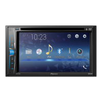
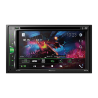
General specifications and reference to the owner's manual.
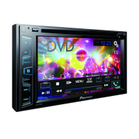
Information on supported disc and content formats, including logos.
Essential checks to perform after completing service to ensure product quality.
Diagram showing the physical locations of main PCBs within the unit.
List of necessary jigs and tools required for specific service tasks.
Instructions for cleaning specific parts before shipping the product.
High-level diagram showing how major units and connectors are interconnected.
Detailed system block diagram illustrating internal component connections and data flow.
Diagram illustrating the power supply system, voltage distribution, and current consumption.
Flowchart detailing the power-on sequence and operational checks.
Step-by-step procedure for inspecting and diagnosing the pickup unit.
Table listing error status, meaning, source, and reset methods.
Description of connector functions and pin assignments.
How to access and display the system's version and state information.
Overview of the service test mode menu and its options.
Method for updating the unit's firmware using a USB memory stick.
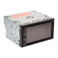
Procedure for removing the monitor assembly from the unit.
Steps to disconnect and remove the monitor PCB from the assembly.
Procedure for removing the key PCB, including latches and holders.
Instructions for removing the DVD mechanism module, including solder shorting.
Steps to remove the heat sink and associated holder.
Procedure for removing the bracket and its holder.
Steps to remove the main mother unit from the chassis.
Important points for assembling, specifically regarding heat radiation sheets.
Identifies assemblies that require adjustment after replacement.
Detailed procedure for performing flicker adjustment via the service mode.
Exploded view illustrating the packing components of the product.
Exploded view of the exterior parts of the unit, shown in sections.
Exploded view of additional exterior parts and cables.
Exploded view of the DVD mechanism module, detailing its components.
Continuation of the exploded view for the DVD mechanism module.
Schematic diagram for the Mother Unit's sense circuitry.
Schematic for the Mother Unit's Bluetooth interface circuitry.
Schematic for the Mother Unit's USB power supply circuitry.
Schematic for the Mother Unit's interface circuitry.
Schematic for the Mother Unit's E.VOL (External Volume) circuitry.
Schematic for the Mother Unit's DDC 2ch (Digital Data Communication) circuitry.
Schematic for the Mother Unit's tuner circuitry.
Schematic for the Mother Unit's PWIC (Power IC) circuitry.
Schematic for the Mother Unit's microcontroller (ucom) circuitry.
Schematic for the Mother Unit's power supply circuits.
Schematic for the Mother Unit's System-on-Chip (SOC) circuitry.
Schematic for the Monitor PCB's interface (IF) circuitry.
Schematic for the Monitor PCB's LCD backlight circuitry.
Schematic for the Monitor PCB's LCD power circuitry.
Schematic for the Monitor PCB's LCD interface circuitry.
Schematic for the Monitor PCB's TCON (Timing Controller) circuitry.
Schematic for the Monitor PCB's isolation circuitry.
Schematic diagram of the relay unit.
Schematic diagram of the key PCB.
Illustrations of expected waveforms for various test points.
PCB connection diagram for the Mother Unit (Side A and Side B).
PCB connection diagram for the Monitor PCB (Side A and Side B).
PCB connection diagram for the Relay Unit (Side A and Side B).
PCB connection diagram for the Key PCB (Side A and Side B).
List of parts included in the product packing.
Table comparing part differences across different model variations.
List of miscellaneous electronic components and their part numbers.
List of resistors with their circuit symbols, part numbers, and locations.
List of capacitors with their circuit symbols, part numbers, and locations.