Do you have a question about the Pioneer AVH-P5000DVD/XN/UC and is the answer not in the manual?
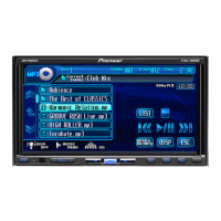
| Display Size | 6.1 inches |
|---|---|
| DVD Playback | Yes |
| Bluetooth | No |
| USB Input | Yes |
| Audio Formats Supported | MP3, WMA, AAC |
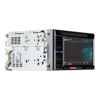
| DIN Size | Double DIN |
| Screen Size | 6.1 inches |
| Touchscreen | Yes |
| Motorized Display | Yes |
| CD Playback | Yes |
| iPod Control | Yes |
| AUX Input | Yes |
| Subwoofer Output | Yes |
| Remote Control | Yes |
| AM/FM Tuner | Yes |
| Video Output | Yes |
| Audio Output | Yes |
| Rear View Camera Input | Yes |
| Video Formats Supported | DivX |
| RCA Outputs | 3 pairs |
| Power Output | 50W x 4 |
| RMS Power Output | 22W x 4 |
| Peak Power Output | 50W x 4 |
General caution statement regarding product operation and handling.
General warning statement about product contents and disposal.
Safety guidelines for qualified service technicians performing repairs.
Conformance to regulations and maintaining a safe servicing environment.
Procedures for maintaining original performance through adjustments.
Guidelines for using specified lubricants, glues, and replacement parts.
Proper cleaning procedures for restoring performance.
Procedures to protect products from transit damage.
General precautions for safe and compliant servicing practices.
Guidelines for using lead-free solder and appropriate soldering irons.
Warning about hot components during operation or servicing.
Technical specifications for power, dimensions, weight, and display.
Supported disc formats and content types.
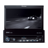
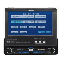
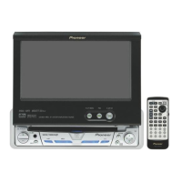
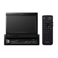
Description of front panel controls and optional remote control.
Diagram illustrating external connections and wiring.
Procedures to confirm product quality after repairs are completed.
Identification and location of various printed circuit boards within the unit.
List of special tools or jigs required for servicing.
Specific cleaning procedures for portions of the product before shipping.
High-level overview of the unit's main functional blocks and interconnections.
Step-by-step guide for diagnosing operational issues.
Procedures for inspecting and testing the pickup unit.
Detailed flowchart for diagnosing specific system failures.
Table listing error codes, meanings, and reset methods.
Explanation of the function of each connector and its pins.
Method to check basic operation without connecting the tuner box.
Procedures and images for entering and operating the DVD test mode.
Procedures for calibrating the touch panel.
Procedures for adjusting monitor settings.
Step-by-step instructions for removing the front grille assembly.
Procedures for separating the drive unit from the chassis assembly.
Step-by-step instructions for removing the DVD mechanism module.
Procedures for removing the front panel holder.
Step-by-step instructions for removing the DVD amplifier unit.
Procedures for removing the monitor PCB (part 1).
Procedures for removing the monitor PCB (part 2).
Precautions for holding the mechanism section during disassembly.
Procedures for removing the module PCB.
Procedures for removing the pickup unit.
Precautions and procedures for DVD adjustment.
Procedures for performing SKEW adjustment on the pickup unit.
Detailed steps for performing pickup unit adjustments.
Adjustment points and procedures for the DVD amplifier unit.
Adjustment items and procedures for the invertor PCB.
Adjustment items and procedures for the monitor PCB.
Procedures for calibrating the touch panel.
Exploded views and parts list for packing components.
Schematic diagram for the DVD amplifier unit (analog section).
Schematic diagram for the DVD amplifier unit (system section).
Schematic diagram for the DVD amplifier unit (power supply section).
Schematic diagram for the iPod connector unit.
Schematic diagram for the keyboard unit.
Schematic diagram for the DVD core unit (part 1).
Schematic diagram for the DVD core unit (part 2).
Schematic diagrams for compound units A and B.
Schematic diagram for the monitor PCB.
Schematic diagram for the monitor PCB (OSD, uCOM).
Schematic diagram for the invertor PCB.
Schematic diagram for the tuner box unit.
PCB connection diagram for the DVD amplifier unit.
PCB connection diagram for the iPod connector unit.
PCB connection diagram for the keyboard unit.
PCB connection diagram for the DVD core unit.
PCB connection diagrams for compound units.
PCB connection diagram for the monitor PCB.
PCB connection diagram for the invertor PCB.
PCB connection diagram for the tuner box unit.
Visual representation of electrical signals at various test points.
List of miscellaneous electronic components and their part numbers.