Do you have a question about the Pioneer AVIC-Z2/XU/UC and is the answer not in the manual?
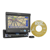
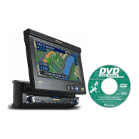
| DVD Playback | Yes |
|---|---|
| CD Playback | Yes |
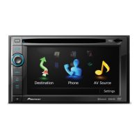
| Bluetooth | No |
| USB Connectivity | No |
| HD Radio | No |
| Power Output | 50W x 4 |
| Rear View Camera Input | Yes |
| Navigation | Built-in |
| Audio Formats Supported | MP3, WMA |
| iPod Connectivity | Yes |
| Sirius Satellite Radio | Sirius Ready |
| Video Output | Yes |
| Steering Wheel Control | Yes |
| Video Formats Supported | DVD |
| Preamp Outputs | 3 (Front, Rear, Subwoofer) |
| XM Radio Ready | Yes |
| Dimensions (W x H x D) | 178mm x 100mm x 160mm (7" x 3-15/16" x 6-5/16") |
Lists parts included in the product packaging.
Details the external parts and assembly of the unit.
Details the external parts and assembly of the unit.
Details the external parts and assembly of the unit.
Exploded view and parts list for the DVD mechanism module.
Lists electrical components for the GPS unit.
Lists electrical components for the audio unit.
Lists electrical components for the Navi Mother Unit.
Lists electrical components for the monitor unit.
General warnings for qualified service technicians.
Chemical content warnings and disposal information.
Precautions for safe servicing and handling of ICs.
Regulations and safe servicing environment guidelines.
Procedures for optimal performance adjustments.
Overall block diagram of the system.
PCB connection diagram for the Audio Unit.
Lists miscellaneous electrical components.
Lists various resistors used in the circuit.
Lists various capacitors used in the circuit.
Diagram showing jig connections for adjustments.
Procedure to verify power supply voltages.
Procedure to verify clock signals.
Procedure to verify the streaming interface.
Procedure to verify the audio circuit.
Procedures for adjusting video levels.
Procedure for adjusting the PLL area.
Adjustment procedures for the monitor unit.
Procedures for adjusting screen flicker.
Service mode for adjusting COM DC and other settings.
Adjustments for various display parameters (brightness, gamma, etc.).
Overview of Mecha service test modes.
Procedure for checking GPS signal reception.
Clearing HDD user region and main memory.
Procedures for disassembling the monitor area.
Steps to remove the DVD mechanism module.
Important precautions for handling the mechanism module.
Description of connector pin functions for various units.
Pin layout and block diagrams for integrated circuits.
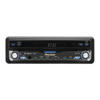
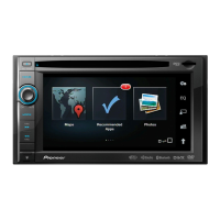
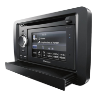
Identifies and describes the names and functions of the parts.
Identifies and describes the functions of the hardware buttons.
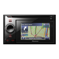
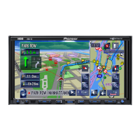
Steps to search for a destination by address.
Information on traffic conditions displayed on the map.
General warnings for qualified service technicians.
Chemical content warnings and disposal information.
Precautions for safe servicing and handling of ICs.
Regulations and safe servicing environment guidelines.
Procedures for optimal performance adjustments.
Guidelines for using specified lubricants and adhesives.
Proper cleaning procedures for optical components.
Instructions for protecting the product during transit.
Exploded view diagram of the product packaging.
Exploded view of the unit's exterior components.
Overall block diagram of the Bluetooth Assy.
PCB connection diagram for the Bluetooth Assy.
Procedure for testing Bluetooth functionality.
Procedure for testing Bluetooth carrier signal.
Diagnostic procedures.
Steps for disassembling the Bluetooth Assy.
Description of connector pin functions for the Bluetooth unit.
Pin layout and block diagrams for integrated circuits.
General information about Bluetooth functionality.
Recommended operating conditions for the unit.