Do you have a question about the Pioneer CLD-1750 and is the answer not in the manual?
Various warnings and details about the laser diode for safe operation.
Identifies and shows various warning labels attached to the unit.
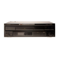
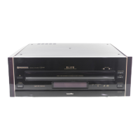
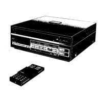
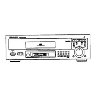
Lists and illustrates parts for the exterior section of the player.
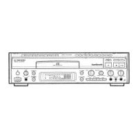
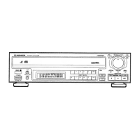
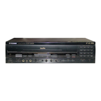
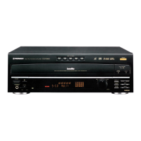
Lists and illustrates components for the front panel assembly.
Lists and illustrates components visible from the top view of the unit.
Lists parts for major internal assemblies like mechanism and clamper.
Lists and illustrates components for the base section of the player.
Lists and illustrates components for the mechanism assembly.
Lists and illustrates components for the chassis section of the player.
Lists and illustrates parts for the servo mechanism base section.
Lists and illustrates parts for the rack section of the player.
Lists and illustrates components of the pickup assembly.
Lists all parts required for packing the player.
Identifies the location and composition of main PCB assemblies.
Explains symbols, abbreviations, and notations used in schematic diagrams.
Shows the complete wiring connections between major components and boards.
Provides the schematic diagram for the System Power Supply (SYPS) assembly.
Lists and illustrates components of the pickup assembly.
Displays signal waveforms for the AFM and Spindle D sections.
Lists pin voltages and shows waveforms for the D. Audio section.
Schematic diagram for the ASCB board, focusing on the D. Audio section.
Schematics for ASCB (part 4/4) and SW1 board assemblies, including D. Audio.
Displays signal waveforms for various ICs in the video section.
Schematics for ASCB (part 2/4) and FG board assemblies.
Schematic diagram for the FLKY (Fluorescent Lamp & Key) assembly.
Schematic diagram for the HEPB (Headphone) assembly.
Schematic diagram for the SHKY (Shuttle & Key) assembly.
Schematic diagram for the PSWB (Power Switch) assembly.
Lists major assemblies with their part numbers.
Lists semiconductor components used on various PCBs.
Lists switches and relays used on PCBs.
Lists inductors, filters, and resistors used on PCBs.
Lists semiconductors, coils, and capacitors for the VDTB board.
Lists semiconductors, relays, coils, resistors, and capacitors for the SCRT board.
Lists components for the Power Switch (PSWB) assembly.
Lists components for the Fluorescent Lamp & Key (FLKY) assembly.
Lists coils and capacitors for the Headphone (HEPB) assembly.
Explains how to enter, operate, and cancel the test mode for player adjustments.
Illustrates and explains the various displays seen on the TV and unit during test mode.
Lists all necessary tools and test equipment for performing adjustments.
Outlines preparatory steps before starting adjustments, including disc insertion.
Details specific adjustments for the ASCB board assembly with procedures and specifications.
Details electrical adjustments for the VDTB board assembly.
Highlights differences in parts between HB and HEZ models.
Details specific part number differences for the SYPS assembly between models.
Provides overall technical specifications for the player's system and laser.
Details specifications for LaserVision, PAL, NTSC, and Compact Discs.
Describes video output levels, audio output levels, and frequency response.
Lists terminal functions and included accessories.
Details operations achievable via the remote control unit for various play modes.
Summarizes player functions like display, playback modes, and special features.
Identifies and explains the function of buttons on the front panel and remote control.
Explains the meaning of various indicators on the player's display window.
| Video Output | Composite Video |
|---|---|
| Dimensions | 17.1 x 14.5 x 4.3 inches |
| Weight | 11.5 lbs |
| Laser Type | Semiconductor Laser |
| Laser Wavelength | 780 nm |
| Video Output Level | 1.0 Vp-p (75 ohms) |
| Power Consumption | 30 W |
| Number of Channels | 2 |
| Dynamic Range | 96 dB |
| Total Harmonic Distortion | 0.003% |
| Output Voltage | 2.0 V |
| Type | CD Player |
| Audio Output | 2-channel |
| Harmonic Distortion | 0.003% |
| Frequency Response | 20 Hz - 20 kHz |