Do you have a question about the Pioneer CLD-99 and is the answer not in the manual?
Covers critical safety checks and precautions for technicians.
Highlights safety-related characteristics of electrical and mechanical parts.
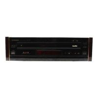
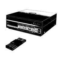
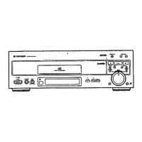
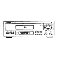
Details external components and the disc tray assembly with part identification.
Highlights construction differences between CLD-99 and CLD-79 models for the top view.
Lists part numbers for the CLD-99/KU/CA model's top view components.
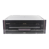
Details construction differences between CLD-99 and CLD-79 models for the front panel.
Lists part numbers for the CLD-99/KU/CA model's front panel assembly.
Highlights construction differences between CLD-99 and CLD-79 models for the bottom view.
Lists part numbers for the CLD-99/KU/CA model's bottom view components.
Notes construction differences between CLD-99 and CLD-79 models for packing.
Lists part numbers for the CLD-99/KU/CA model's packing accessories.
Presents the overall wiring diagram for various assemblies.
Details the SYPS (System Power Supply) assembly schematic and warnings.
Provides information on the FL display tube, including anode grid and pin assignments.
Details the anode grid assignments for the FL display tube.
Lists the pin assignments for the FL display tube.
Shows the SACB assembly audio section schematic for CLD-99.
Shows the SACB assembly audio section schematic for CLD-79.
Presents waveforms and voltage measurements for FTS and CONT sections.
Presents the SACB assembly audio section schematic for CLD-99.
Presents the SACB assembly audio section schematic for CLD-79.
Details the SACB assembly video section.
Explains the DVDB assembly (part 1/2) video section.
Details the video section of the DVDB assembly (part 1/2).
Covers the TDYC assembly (CLD-99 ONLY) including waveforms.
Continues TDYC assembly details, covering DVDB assembly (part 2/2).
Details the DVDB assembly (part 2/2) including its block diagram.
Lists major assemblies and their corresponding part numbers.
Lists semiconductors used in the SYPS assembly.
Lists semiconductors used in the SACB assembly.
Lists resistor part numbers and their corresponding values.
Lists capacitor part numbers and their corresponding values.
Explains how self-diagnostic functions display error codes and their meanings.
Details the format of mechanism switch information sent during error occurrences.
Guides on how to start, cancel, and operate the player in test mode.
Lists necessary equipment and important precautions before starting adjustments.
Advises on careful adjustment of centering and TAN screws within their range.
Provides notes on adjusting centering for sides A and B based on error waveforms.
Warns about potential bumping between mechanism stopper and RACK assy during adjustment.
Recommends cleaning the lens and replacing the carriage assy when adjusting the pickup.
Shows diagrams indicating the locations of adjustment points on various PCBs.
Provides detailed step-by-step procedures for mechanical adjustments.
Guides on performing electrical adjustments for various signal levels.
Lists pin functions for the PD0205D microcomputer, crucial for mechanism control.
Details the block diagram and pin functions for the GGC1019 IC.
Explains the block diagram and pin functions for the GGC1064 IC.
Provides the block diagram and pin functions for the CXD1171M D/A converter.
Details the block diagram and pin functions for the UPD42280GU-30 memory IC.
Describes the mode control system, including microcomputer interface and communication sequences.
Explains the operations executed when the Direct CD switch is set to ON.
Outlines the functions of the mode microcomputer and the Film Mode operation.
Details the digital video signal processing for movement-adaptable Y/C separation.
Presents the overall block diagram of the CLD player's main sections.
Illustrates the block diagram specifically for the video section of the player.
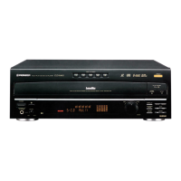
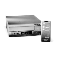
Identifies and describes the controls and indicators on the front panel of the unit.
Explains the indicators and displays on the front panel, including status and time information.
Lists the technical specifications for the CLD-99 model.
Lists the technical specifications for the CLD-79 model.
| Type | LaserDisc Player |
|---|---|
| Video Output | Composite, S-Video |
| Laser Type | Semiconductor Laser |
| Laser Wavelength | 780 nm |
| Disc Format | CD |
| Audio Output | Analog, Digital Coaxial |
| Frequency Response | 4 Hz - 20 kHz |