This document is a service manual for the Pioneer CLD-D790, CLD-D590, and CLD-D390 CD/CDV/LD players. It provides comprehensive information for servicing, maintenance, and operation of these devices.
Function Description:
The Pioneer CLD-D790, CLD-D590, and CLD-D390 are multi-format players capable of handling CD, CDV, and LD discs. These devices are designed to provide high-quality audio and video playback from these various disc types. The manual details the internal components and their interconnections, allowing for systematic troubleshooting and repair. It covers aspects such as safety information, exploded views of parts, schematic diagrams, PCB connection diagrams, waveforms, voltage measurements, block diagrams, FL information, panel facilities, and specifications.
Important Technical Specifications:
The players operate on AC 110-240V, 50/60 Hz power.
- Power Consumption:
- CLD-D790: 39 W
- CLD-D590: 39 W
- CLD-D390: 37 W
- Dimensions (W x H x D): 420 (W) x 405 (D) x 133 (H) mm (excluding protruding cables, etc.)
- Weight:
- CLD-D790: 6.7 kg
- CLD-D590: 6.6 kg
- CLD-D390: 6.6 kg
- Laser: Semiconductor laser, wavelength 780 nm. The device includes a Class 1 laser diode emitting invisible infrared radiation, which is dangerous to eyes. Servicing should only be performed by specially instructed personnel.
- Video Output (2 pairs): 1 Vp-p (75Ω when loaded, synchronous negative) RCA jacks.
- S-Video Output (2 pairs) (CLD-D790/CLD-D590 only): Y (luminance) output level 1 Vp-p (75 Ω), C (chroma) output level 286 mVp-p (75 Ω) S-Video jacks.
- Audio Output (2 pairs): Output level 200 mVrms (1 kHz, 40%), During digital audio output 200 mVrms (1 kHz, -20 dB) RCA jacks.
- Digital Audio Characteristics (CLD-D790/CLD-D590):
- Frequency response: 4 Hz to 20 kHz
- S/N ratio: 115 dB (EIAJ)
- Dynamic range: 98 dB (EIAJ)
- Total harmonic distortion: 0.003% (EIAJ)
- Wow and flutter: Below measurable limits (±0.001% W. PEAK) or lower (EIAJ)
- Digital Audio Characteristics (CLD-D390):
- Frequency response: 4 Hz to 20 kHz
- S/N ratio: 107 dB (EIAJ)
- Dynamic range: 98 dB (EIAJ)
- Total harmonic distortion: 0.005% (EIAJ)
- Wow and flutter: Below measurable limits (±0.001% W. PEAK) or lower (EIAJ)
- Operating Temperature: +5°C to +35°C
- Operating Humidity: 5% to 85% (no condensation)
Usage Features:
The manual provides detailed information on the front panel controls and remote control unit functions for each model.
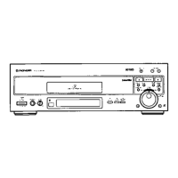
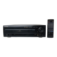
- Front Panel (CLD-D790): Includes LD Open/Close button, Fast Forward (FWD) button, Play button, CD Open/Close button, Fast Reverse (REV) button, Disc Side A, B button, Power switch/Standby indicator, Picture Control button (CLD-D790 only), Display OFF button, Quick Turn button, Display window, and Stop button.
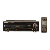
- Remote Control Unit (CLD-D790): Features Power, Open/Close, Audio D/A, Repeat, Display, Clear, Lighting, Program (PGM), Chapter/Time (CHP/TM), Last Memory, Random, Multi-Speed, Skip, Hilite/Intro, Stop, Play, Pause, Scan, Jog Mode, Disc Side A/B, Jog dial, and Shuttle ring.
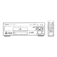
- Remote Control Unit (CLD-D590): Features Power, Open/Close, Audio D/A, Repeat, Display, Clear, Hilite/Intro, Program (PGM), Random, Chapter/Time (CHP/TM), Multi-Speed, Step, Skip, Stop, Play, Pause, Scan, Last Memory, Disc Side A/B, and Scan control.
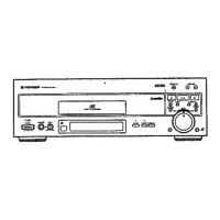
- Remote Control Unit (CLD-D390): Features Last Memory, Open/Close, Power, Clear, Numeric, Program (PGM), Hilite/Intro, Chapter/Time (CHP/TM), Random, Audio, Repeat, Display, Stop, Play, Pause, Scan, Multi-Speed, Step, and Disc Side A/B.
- Test Mode Operations: The manual outlines specific test modes for diagnosis and adjustment, including "Test Mode: ON," "Test Mode: DISC SET" (with and without tray), "Test Mode: PLAY," and "Test Mode: OFF." These modes are crucial for technicians to verify proper functionality and perform adjustments.
Maintenance Features:
The manual is primarily a service guide, offering extensive information for maintenance and repair.
- Safety Information: Emphasizes caution regarding invisible laser radiation and the need for servicing by specially instructed personnel.
- Exploded Views and Parts List: Provides detailed diagrams of the device's internal components with corresponding part numbers, facilitating identification and replacement of parts. This includes breakdowns for the main unit, disc tray, top section, front panel, bottom section, servo mechanism, loading mechanism, and carriage assembly.
- Schematic Diagrams: Comprehensive circuit diagrams for various assemblies, including overall connections, power supply, FLKY, KEYB, PWSB, MOTHER, and CNNB assemblies. These diagrams are essential for understanding the electrical flow and troubleshooting circuit issues.
- PCB Connection Diagrams: Illustrates the layout and connections of printed circuit boards (PCBs), such as PKSB, FG, TNSB, BISB, LMSB, Power Supply, FLKY, KEYB, PWSB, MOTHER, CNNB, and YCPB assemblies, aiding in component location and repair.
- Waveforms and Voltage: Provides expected waveforms and voltage measurements at key test points on the MOTHER ASSY, crucial for diagnosing electrical faults.
- Adjustments: Detailed procedures for mechanical and electrical adjustments, including:
- Mechanical Adjustments: Tilt Offset, Tangential Direction Angle (Side A/B), Spindle Motor Centering (Side A/B), Crosstalk Check and Fine Tilt Offset (Side A/B), Focus Servo Loop Gain, and Tracking Servo Loop Gain. These adjustments ensure precise disc reading and playback.
- Electrical Adjustments: Master Clock Adjustment and Output Video Level Adjustment, vital for maintaining video signal quality.
- Self-Diagnostic Functions: Explains how the device's microprocessor displays error codes on the TV screen and front panel fluorescent display, aiding in quick problem identification. A table lists error codes, conditions, and probable causes.
- Ageing Mode: Describes a mode for continuous operation (ageing) to test reliability and identify intermittent faults, with procedures for LD, CD/CDV, and no-disc scenarios.
- Disassembly/Assembly: Step-by-step instructions with illustrations for disassembling and reassembling the disc tray, mother assy, and flexible cables, ensuring proper handling during repairs.
- FL Information: Details the fluorescent display (FL) information, including anode grid assignment and pin assignment, useful for troubleshooting display issues.
- Block Diagrams: Overall block diagrams and specific block diagrams for the line digital comb filter, system bus, focus servo, TRKG & SLDR, and video & TBC blocks, providing a high-level overview of the device's architecture.
- Diagnostic Land Mark and Pattern: Illustrates diagnostic points and signal flow on the MOTHER ASSY for focus servo, TRKG servo, and RF/video systems.