Do you have a question about the Pioneer DEH-3050MP/XN/ES and is the answer not in the manual?
| Brand | Pioneer |
|---|---|
| Model | DEH-3050MP/XN/ES |
| Category | Car Receiver |
| Language | English |
Details about the laser diode's wavelength, output power, and safety warnings.
Guidelines for safe servicing, including handling ICs and power.
Instructions for using lead-free solder and suitable soldering irons.
Details on power source, dimensions, weight, and tuner specifications.
Maximum and continuous power output, tone controls, and load impedance.
System, usable discs, signal-to-noise ratio, and WMA/MP3/WAV formats.
Frequency range, usable sensitivity, and signal-to-noise ratio for FM.
Specifications for AM tuner and infrared remote control functions.
Supported disc types and content formats for playback.
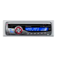
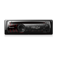
Description of buttons and ports on the head unit's front panel.
Explanation of the remote control's operation, similar to head unit buttons.
Details on connecting wires, fuses, antenna, speakers, and power.
Procedures to confirm after repairs to ensure proper product quality.
Identification of main PCB units within the system.
List of special tools (jigs) and greases used for servicing.
High-level functional overview of the Tuner Amp and CD Core units.
Step-by-step process for power-on and source selection diagnosis.
List of error codes, their display, and potential causes for CD operation issues.
Details on the function of each pin for the rear output and wired remote connectors.
Procedures for entering and exiting CD test mode for adjustments.
Detailed flowchart illustrating operations and key functions within CD Test Mode.
Procedure to check and adjust the grating angle after replacing the pickup unit.
Steps for removing the outer case and grille assembly.
Instructions for disconnecting and removing the CD mechanism module.
Procedure for removing the tuner amplifier unit from the chassis.
Detailed steps for removing the mechanism unit's upper and lower frames.
Steps to remove the CD core unit by unsoldering and unscrewing.
Procedure for removing the pickup unit from the carriage mechanism.
Procedure to confirm clock signal output frequency for proper operation.
List of items included in the product packaging.
Detailed list of parts included in the product's packaging.
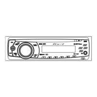
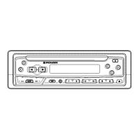
Diagram illustrating the external components and their identification numbers.
List of part numbers and descriptions for external components.
Diagram and list of parts for the CD mechanism module.
Detailed list of part numbers for the CD mechanism module components.
Schematic showing the interconnections between major units like Tuner and CD.
Schematic diagram for the keyboard unit, showing ICs, buttons, and LCD connections.
Schematic for the CD mechanism, including pickup, motors, and switches.
Illustrations of various signal waveforms from the CD core unit for analysis.
Diagram showing PCB layout and connections for the Tuner Amp Unit.
PCB layout and component connections for the keyboard unit.
PCB layout and connections for the CD Core Unit, including pickup and motor drivers.
List of electrical components with their part numbers and circuit symbols.