Do you have a question about the Pioneer DEH-3350UB/XNES and is the answer not in the manual?
Important safety guidelines for technicians to follow during repair procedures.
Essential safety measures to ensure compliance with regulations and safe servicing.
Procedures for optimizing product performance and confirming specifications.
Guidance on using correct materials for repairs.
Instructions for cleaning components to restore performance.
Steps to protect the product during transit.
General safety guidelines and operational rules for servicing.
Specific instructions and precautions for lead-free soldering.
Detailed technical data and performance metrics of the unit.
Information on supported media types and playback formats.
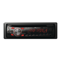
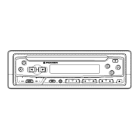
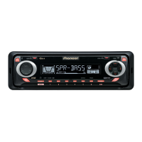
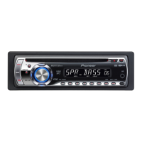
Description of front panel controls, buttons, and display indicators.
Visual guide for unit wiring and external connections.
Verification steps to confirm repair quality and functionality.
Identification and placement of the main Printed Circuit Boards within the unit.
A catalog of necessary special tools and fixtures for service operations.
Procedures for cleaning the unit before final shipment.
A high-level overview of the unit's internal functional blocks.
Flowchart detailing the unit's power-on sequence.
A reference guide detailing error codes and their potential causes.
Explains the purpose and pin assignments of various connectors.
Instructions for accessing and using the display test mode.
A diagnostic mode for testing and adjusting the CD mechanism.
Steps to safely detach the front panel of the unit.
Procedure for disassembling and removing the CD mechanism.
Specific procedures for calibrating and adjusting the CD playback system.
Method to verify the grating angle after PU unit replacement.
Procedure to check the PCL output signal's frequency and waveform.
Exploded view illustrating how the unit is packed for shipment.
A list of all parts included in the product packaging.
Exploded view showing the external components of the unit.
A detailed list of parts for the unit's exterior.
A table comparing part differences across various models.
Exploded view detailing the assembly of the CD mechanism.
A list of all parts specific to the CD mechanism.
Schematic showing the circuit of the Tuner Amplifier section.
Schematic detailing the circuitry of the Keyboard unit.
Schematic for the CD Core unit.
Visual representations of signal patterns used for troubleshooting.
PCB layout and connection details for the Tuner Amp unit.
PCB layout and connection details for the Keyboard unit.
PCB layout and connection details for the CD Core unit.
A detailed inventory of electrical components and their specifications.
| CD Playback | Yes |
|---|---|
| USB Input | Yes |
| Aux Input | Yes |
| Bluetooth | No |
| Equalizer | 5-Band Graphic Equalizer |
| Supported Formats | MP3, WMA, WAV |
| Detachable Faceplate | Yes |
| RMS Power Output | 22 W x 4 |
| USB Direct Control | Yes |
| Display Type | LCD |
| Remote Control | Yes |
| Preset EQ | Yes |
| Subwoofer Output | Yes |
| Preamp Voltage | 2V |
| Power Output | 50 Watts x 4 Channels |
| Tuner | AM/FM |
| Display | LCD |
| Pre-Outs | 1 Pair |
| Preamp Outputs | 2-channel |