Do you have a question about the Pioneer DEH-3400UB/XNUC and is the answer not in the manual?
| RMS Power Output | 22W x 4 |
|---|---|
| CD Playback | Yes |
| USB Input | Yes |
| Aux Input | Yes |
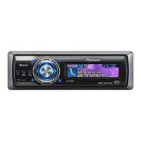
| Bluetooth | No |
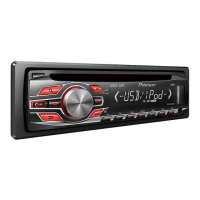
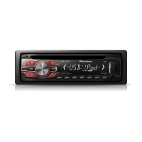
| Supported Audio Formats | MP3, WMA |
| Detachable Faceplate | Yes |
| Power Output | 50W x 4 |
| Tuner | FM/AM |
| Display | LCD |
Important warnings for qualified service technicians regarding safe repair practices.
Warning about potential cancer or birth defects from chemicals used in the product.
Cautionary measures for handling and testing laser diodes to prevent eye damage.
Details on the product's classification as a Class 1 laser product per safety standards.
Warning regarding invisible laser radiation when covers are removed; avoid optical instruments.
Caution that servicing should only be performed by specially instructed persons.
Adherence to regulations, power off before unplugging connectors, ESD protection.
Guidelines for using lead-free solder, appropriate soldering iron tip temperatures.
Technical details including power source, dimensions, weight, audio output, and tuner ranges.
Information on compatible disc types and supported audio file formats (MP3, WMA, WAV).
Instructions on how to secure the front panel using the supplied screw.
Procedures to confirm customer complaints are resolved and product operates normally post-repair.
Identification and location of main PCBs within the unit, including Tuner Amp, Keyboard, and CD Core.
List of specialized jigs and tools required for specific service procedures.
Recommended steps and tools for cleaning critical components like CD pickup lenses before shipping.
Step-by-step guide for diagnosing unit issues, starting from power-on.
Detailed list of error codes displayed for CD operation failures and their possible causes.
Pin assignments and functions for various connectors on the unit's rear panel.
Procedure to enter and navigate test modes for checking system information and display functions.
Detailed flowchart and operations for testing CD mechanism functions and adjustments.
Steps for removing and reassembling the front panel and its components.
Instructions for removing the CD mechanism module from the main unit.
Steps for removing the Tuner Amp Unit from the chassis, including attention points.
Proper methods for handling the mecha unit and detailed steps for PU unit removal.
Cautions and steps for performing CD mechanism adjustments, including test mode entry.
Procedure to check and adjust the grating angle after replacing the pickup unit.
Steps to confirm PCL output signal and check the resonator if the clock signal is abnormal.
Illustration and list of parts included in the product packaging.
Illustrated breakdown of exterior components with corresponding part numbers.
Detailed list and diagram of all parts comprising the CD mechanism module.
Detailed circuit diagram for the Tuner Amp Unit, showing component interconnections.
Circuit diagram for the Keyboard Unit, illustrating its electronic components and connections.
Circuit diagram for the CD Core Unit, detailing its components and functional blocks.
Visual representations of key signal waveforms for diagnostic purposes.
Layout diagram showing component placement and connections on the Tuner Amp Unit PCB.
Layout diagram for the Keyboard Unit PCB, indicating component positions.
Layout diagram of the CD Core Unit PCB, showing component placement.