Do you have a question about the Pioneer DEH-34UB/XNUC and is the answer not in the manual?
| CD Playback | Yes |
|---|---|
| Bluetooth | No |
| Detachable Face | Yes |
| MP3 Playback | Yes |
| WMA Playback | Yes |
| AAC Playback | Yes |
| Number of Channels | 4 |
| Power Output | 50 W x 4 Channels |
| RMS Power Output | 22W x 4 |
| Tuner | AM/FM |
| Aux Input | Yes |
| Playback Media | USB |
General safety and handling guidelines for servicing the unit.
Guidelines for using lead-free solder and appropriate soldering techniques.
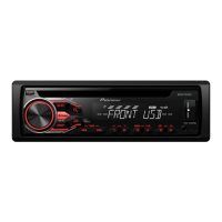
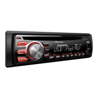
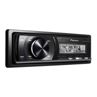
Detailed technical specifications for the CD RDS receiver models.
Information on supported disc and content formats for playback.
Essential checks to confirm successful service and product quality.
Diagrams showing the locations of key Printed Circuit Boards (PCBs).
Flowchart detailing the operational checks for diagnosing issues.
List of error codes and their corresponding causes and troubleshooting steps.
Description and pin assignments for all external connectors on the unit.
Mode for checking system microcomputer version and display elements.
Mode for testing and adjusting CD mechanism functions and performance.
Procedures and precautions for adjusting CD mechanism settings.
Procedure to check and verify the grating angle after PU unit replacement.
Exploded view of the unit's exterior components and their part numbers.
Exploded view of the CD mechanism module and its component parts.
Schematic diagram detailing the Tuner Amplifier unit circuitry.
Schematic diagram detailing the Keyboard unit circuitry.
Schematic diagram detailing the CD Core Unit (S11.6STD) circuitry.
Illustrations of various signal waveforms for troubleshooting and analysis.
PCB connection diagram for the Tuner Amp Unit, showing component placement.
PCB connection diagram for the CD Core Unit (S11.6STD), showing component placement.