Do you have a question about the Pioneer DEH-P510UB and is the answer not in the manual?
Covers general cautions, warnings, and service precautions for safe operation and repair.
Specific safety measures for technicians servicing the unit, especially laser diode handling.
Caution regarding battery replacement risks like explosion and proper handling.
Ensures product safety compliance, safe environment, and proper repair procedures.
Guidelines for product adjustments and confirmation of specifications.
Guidance on using specified lubricants, glues, and correct replacement parts.
Procedures for cleaning parts to restore performance, like optical pickups.
Instructions for setting shipping mode or installing screws for transit protection.
General guidelines for safe servicing, handling ICs, and parts.
Information on using lead-free solder and appropriate soldering iron temperatures.
Detailed technical specifications for audio, tuner, USB, and amplifier features.
Information on supported disc and content formats like CD, iPod, and iPhone.
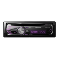
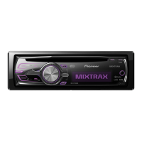
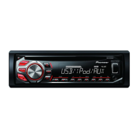
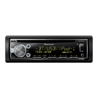
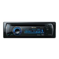
Description of controls and ports on the head unit's front panel.
Diagrams illustrating external connections for speakers, amplifiers, and accessories.
Steps to detach the main outer case of the unit.
Procedure for removing the CD mechanism assembly.
Procedure for removing the tuner amp assembly.
Steps to disassemble the mechanism unit by removing frames and components.
Procedures and cautions for CD mechanism adjustments and test modes.
Method to verify grating angle after pickup unit replacement.
Verifying PCL clock signal frequency and potential X'tal replacement.
Exploded view and parts list for product packaging.
Exploded view and parts list for external components of the head unit.
Exploded view and parts list for more external components, including controls.
Exploded view and parts list for the CD mechanism module components.
Schematic diagram for the tuner amplifier assembly, including reference maps.
Schematic diagram for the keyboard unit, detailing button and interface connections.
Schematic diagram for the CD mechanism module, showing logic and component connections.
PCB connection diagram for the tuner amplifier assembly, showing layout and connectors.
PCB connection diagram for the keyboard unit, illustrating component layout and pinouts.
PCB connection diagram for the CD core unit, showing component layout and pinouts.
List of miscellaneous components like ICs, transistors, diodes, and switches.
| DIN Size | Single DIN |
|---|---|
| Detachable Face | Yes |
| RMS Power Output | 50W x 4 |
| Sub Preamp Output | Yes |
| iPod Compatibility | Yes |
| USB Input | Yes |
| AUX Input | Yes |
| HD Radio | No |
| Satellite Radio Ready | Yes |
| Bluetooth Compatibility | No |
| Channels | 4 |
| USB Direct Control for iPod/iPhone | Yes |
| Subwoofer Control | Yes |
| Steering Wheel Remote Control | Optional |
| CD Playback | Yes |
| AM/FM Tuner | Yes |
| MOSFET Power Supply | Yes |
| RMS Power Bandwidth | 20Hz - 20kHz |
| Max Power Output | 50W x 4 |
| Preset Stations | 18 FM, 6 AM |
| EQ Bands | 5 |