
Do you have a question about the Pioneer DEH-P7950UB/XN/ES and is the answer not in the manual?
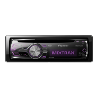
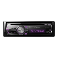
| Model | DEH-P7950UB/XN/ES |
|---|---|
| DIN Size | 1 DIN |
| Channels | 4 |
| Max Power Output | 50 W x 4 |
| RMS Power Output | 22 W x 4 |
| Tuner | AM/FM |
| CD Playback | Yes |
| MP3 Playback | Yes |
| WMA Playback | Yes |
| AAC Playback | Yes |
| USB Port | Yes |
| Bluetooth | No |
| Equalizer | Yes |
| Preamp Outputs | 3 (Front, Rear, Subwoofer) |
| Preamp Voltage | 4 V |
| Sub Preamp Output | Yes |
| Auxiliary Input | Yes |
| Built-in DSP | Yes |
| iPod Compatibility | Yes |
| Detachable Face | Yes |
| Remote Control | Yes |
| CEA-2006 Compliant | Yes |
| Satellite Radio Ready | Yes |
| HD Radio | No |
| RMS Power Bandwidth | 20 Hz - 20 kHz |
Precautions for safe servicing, handling, and general safety aspects.
Exploded view and parts list for the CD mechanism module.
Illustrates the overall system architecture and functional blocks.
Diagram showing interconnections between major system units.
Cautions and step-by-step guide for adjusting the CD mechanism.
Procedure to check pickup unit grating angle and phase difference.
List of error codes, their meanings, and potential causes for CD operation.
Details on entering and using the test mode for various functions and updates.




 Loading...