EasyManua.ls Logo

Pioneer DEH-P750MP - User Manual

Pioneer DEH-P750MP
93 pages
Print Icon
To Next Page IconTo Next Page
Loading...
PIONEER CORPORATION 4-1, Meguro 1-Chome, Meguro-ku, Tokyo 153-8654, Japan
PIONEER ELECTRONICS (USA) INC. P.O.Box 1760, Long Beach, CA 90801-1760 U.S.A.
PIONEER EUROPE NV Haven 1087 Keetberglaan 1, 9120 Melsele, Belgium
PIONEER ELECTRONICS ASIACENTRE PTE.LTD. 253 Alexandra Road, #04-01, Singapore 159936
C PIONEER CORPORATION 2003
K-ZZD. APR. 2003 Printed in Japan
ORDER NO.
CRT3050
MULTI-CD CONTROL HIGH POWER CD/MP3/WMA PLAYER WITH FM/AM TUNER
DEH-P750MPXN/UC
Service
Manual
DEH-P750MP/XN/UC
For details, refer to "Important symbols for good services".
DEH-P7500MPXN/UC
DEH-P7550MPXN/ES
- This service manual should be used together with the following manual(s):
Model No. Order No. Mech. Module Remarks
CX-3057 CRT3026 S10MP3 CD Mech. Module:Circuit Description, Mech.Description, Disassembly
w
w
w
.
x
i
a
o
y
u
1
6
3
.
c
o
m
Q
Q
3
7
6
3
1
5
1
5
0
9
9
2
8
9
4
2
9
8
T
E
L
1
3
9
4
2
2
9
6
5
1
3
9
9
2
8
9
4
2
9
8
0
5
1
5
1
3
6
7
3
Q
Q
TEL 13942296513 QQ 376315150 892498299
http://www.xiaoyu163.com
Question and Answer IconNeed help?

Do you have a question about the Pioneer DEH-P750MP and is the answer not in the manual?

Summary

Exploded Views and Parts List

Packing Exploded View and Parts List

Lists parts for unit packaging, including bags, cartons, and protective materials.

Exterior Exploded View and Parts List for DEH-P7500 Series

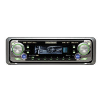
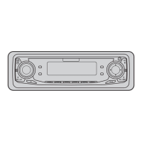
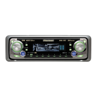
Exploded view and parts list for exterior components of DEH-P7500MP/XN/UC models.

Exterior Exploded View and Parts List for DEH-P7550 MP

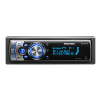
Exploded view and parts list for exterior components of the DEH-P7550MP/XN/ES model.

CD Mechanism Module Exploded View and Parts List

Detailed exploded view and parts list for the CD mechanism module.

Block Diagram and Schematic Diagram

System Block Diagram

High-level block diagram showing the interconnections of major functional units like Tuner and CD.

Overall Unit Connection Diagram

Diagram illustrating signal flow and connections between key units (Tuner, CD, Panel, Controller).

Keyboard Unit PCB Connection Diagram

PCB connection diagram for the keyboard unit, showing component layout and electrical routing.

CD Mechanism Module PCB Connection Diagram

PCB connection diagram for the CD mechanism module, detailing component placement and signals.

PCB Connection Diagram

Tuner Amp Unit PCB Connection Diagram

PCB layout and connection diagram for the Tuner Amplifier unit.

Keyboard Unit PCB Connection Diagram

PCB layout and connection diagram for the Keyboard Unit (Side A and B).

Panel Unit PCB Connection Diagram

PCB layout and connection diagram for the Panel Unit (Side A and B).

CD Mechanism Module PCB Connection Diagram

PCB layout and connection diagram for the CD Mechanism Module.

Electrical Parts List

Adjustment

Jig Connection Diagram for Adjustment

Diagram showing the physical connection of test jigs to the Tuner, Panel, and Keyboard units.

OEL Unit Adjustment Procedure

Procedure for adjusting the OEL unit using a digital multi-meter and specific VR components.

System Microcomputer Test Program

Description of the PCL output test mode for the system's microcomputer.

CD Adjustment Procedures and Notes

Cautions, test mode entry/exit, and specific notes for performing CD mechanism adjustments.

Grating Check After Pickup Unit Replacement

Procedure to check grating angle after replacing the PU unit, including symptoms and method.

Error Mode Identification and Causes

Lists error codes, classifications, contents, and causes for operational errors.

OEL Screensaver Studio Application Usage

Information on using the GGV1131 application for OEL display image file creation and conversion.

General Information

Diagnosis Procedures

General diagnostic information including disassembly steps for major units.

Connector Pinout and Function Descriptions

Description of the function of each pin for various connectors on the rear panel.

Integrated Circuit (IC) Pin Functions

Detailed pin functions and descriptions for various ICs used in the unit.

Unit Operational Flow Chart

Flow chart illustrating the sequence of operations for power on and source selection.

Cleaning Procedures

Instructions for cleaning CD pickup lenses using specified cleaning tools before shipping.

Operations

Connection Diagram

SAFETY INFORMATION

CD Section Precaution

Precautions for handling the CD pickup unit, including ESD treatment.

Pioneer DEH-P750MP Specifications

General IconGeneral
BrandPioneer
ModelDEH-P750MP
CategoryCar Receiver
LanguageEnglish

Related product manuals