EasyManua.ls Logo

Pioneer DEH-P900R User Manual

Pioneer DEH-P900R
89 pages
To Next Page IconTo Next Page
Page #1 background imageLoading...
Page #1 background image
PIONEER ELECTRONIC CORPORATION 4-1, Meguro 1-Chome, Meguro-ku, Tokyo 153-8654, Japan
PIONEER ELECTRONICS SERVICE INC. P.O.Box 1760, Long Beach, CA 90801-1760 U.S.A.
PIONEER ELECTRONIC [EUROPE] N.V. Haven 1087 Keetberglaan 1, 9120 Melsele, Belgium
PIONEER ELECTRONICS ASIACENTRE PTE.LTD. 253 Alexandra Road, #04-01, Singapore 159936
C PIONEER ELECTRONIC CORPORATION 1999
K-ZZB. APR. 1999 Printed in Japan
ORDER NO.
CRT2324
MULTI-CD/DAB CONTROL DSP HIGH POWER CD PLAYER WITH RDS TUNER
DEH-P900R UC
Service
Manual
CONTENTS
1. SAFETY INFORMATION ............................................2
2. EXPLODED VIEWS AND PARTS LIST.......................3
3. BLOCK DIAGRAM AND SCHEMATIC DIAGRAM ...10
4. PCB CONNECTION DIAGRAM ................................32
5. ELECTRICAL PARTS LIST ........................................44
6. ADJUSTMENT..........................................................54
7. GENERAL INFORMATION .......................................58
7.1 DIAGNOSIS ........................................................58
7.1.1 TEST MODE..............................................58
7.1.2 DISASSEMBLY .........................................62
7.2 IC ........................................................................67
8. OPERATIONS AND SPECIFICATIONS.....................83
- See the separate manual CX-916(CRT2300) for the CD mechanism description, disassembly and circuit
description.
- The CD mechanism employed in this model is one of S8 series.
DEH-P900R/UC
DEH-P9050 ES
MULTI-CD CONTROL DSP HIGH POWER CD PLAYER WITH FM/AM TUNER
SERVICE PRECAUTION
In the first production, the following parts had been mounted temporarily to support the microcomputer
<DEH-P900R/UC> IC601 (PD5483A): R591 (RS1/16S473J), R592 (RS1/16S102J), and IC591 (Non spare part).
When replacing IC601 PD5483A, use PD5483B as IC601, and then remove the 3 parts listed above.
<DEH-P9050/ES> IC601 (PD5484A): R591 (RS1/16S473J), R592 (RS1/16S102J), and IC591 (Non spare part).
When replacing IC601 PD5484A, use PD5484B as IC601, and then remove the 3 parts listed above.

Table of Contents

Question and Answer IconNeed help?

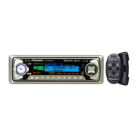
Do you have a question about the Pioneer DEH-P900R and is the answer not in the manual?

Pioneer DEH-P900R Specifications

General IconGeneral
Channels4
TunerAM/FM
Radio Data System (RDS)Yes
CD PlayerYes
CD-R PlaybackYes
CD-RW PlaybackYes
MP3 PlaybackYes
WMA PlaybackNo
ID3 Tag DisplayYes
Display TypeLCD
Detachable FaceplateYes
Built-in CrossoverYes
Time AlignmentYes
Subwoofer ControlYes
Remote ControlYes
AUX InputNo
USB PortNo
BluetoothNo
Max Power Output50 Watts x 4
Preamp Voltage4V
Preamp Outputs3 Pairs
RMS Power Output22 Watts x 4

Summary

Service Precautions

Safety Information

CAUTION Statements

Cautions for qualified service technicians regarding product repair.

WARNING Statements

Warning about lead and chemicals causing cancer/birth defects.

CD Player Service Precautions

Pickup Unit Handling and ESD

Handling precautions for the pickup unit, including ESD protection.

Disassembly Power Safety

Turn off power during disassembly to prevent IC damage.

Grating Check Procedure

Check the grating after changing the service pickup unit.

Exploded Views and Parts Lists

Packing Section Parts

Exploded view and parts list related to product packing.

Exterior Views and Parts Lists

Exterior Section Parts List

Detailed parts list for the exterior components.

CD Mechanism Module Details

CD Mechanism Parts List

Detailed parts list for the CD mechanism module.

System Diagrams

Block Diagram

High-level overview of the system's functional blocks.

Overall Connection Diagram

Diagram showing interconnections between major units and signals.

FM/AM Tuner Unit Schematic

Keyboard Unit Schematic

DSP Unit Schematic

ASL Unit Schematic

CD Mechanism Module Schematic

Waveform Analysis

Focus and Tracking Waveforms (FD, FO+, TE, TD)

Waveform analysis for focus and tracking signals in various modes.

Playback and Signal Waveforms (FE, MD, RFI, MIRR)

Waveform analysis for playback and signal integrity.

Waveforms (Continued)

Test Mode Waveforms (TE, TD, TEC)

Waveform analysis for TE, TD, TEC signals in test modes.

Playback Waveforms (MD, EFM)

Waveform analysis for MD and EFM signals during normal play.

Signal Integrity Waveforms (PLCK, SCKO, Dout, LRCK, VD)

Waveform analysis for signal integrity checks.

Waveforms (Continued)

AGC and Defect Waveforms (FE, FD, TE, TD, RFI, HOLD)

Waveform analysis for AGC and defect conditions.

PCB Connection Diagrams

Tuner Amp Unit PCB Layout

PCB layout for the Tuner Amp Unit, showing component placement.

FM/AM Tuner Unit PCB Diagrams

Keyboard Unit PCB Diagrams

DSP Unit PCB Diagrams

ASL Unit PCB Diagrams

Switch and MIC Jack PCB Diagrams

Switch PCB Layout

PCB layout for the Switch PCB.

MIC Jack PCB Layout

PCB layout for the MIC Jack PCB.

CD Mechanism Module PCB Diagrams

Electrical Parts List

Tuner Amp Unit Model Contrast

Adjustment Procedures

CD Mechanism Adjustment

Procedures and precautions for adjusting the CD player mechanism.

Pickup Unit Grating Check

Procedure to check pickup unit grating angle and symptoms of maladjustment.

CD Adjustment Flow Chart

Grating Check Procedure

Symptoms of Mal-adjustment

Symptoms indicating maladjustment of the pickup unit's grating angle.

Method for Grating Check

Method for checking the grating angle, including equipment and mode.

Checking Procedure Steps

Step-by-step procedure for checking the pickup unit's grating angle.

Grating Waveform Examples

General Information and Diagnosis

Test Mode Overview

Description of the test mode for diagnostics and adjustments.

Error Code Reference

List of error codes, their causes, and descriptions.

Test Mode Operations

New Test Mode Shifting Procedure

Information on shifting to and operating the new test mode.

Test Mode Key Functions

Table mapping keys to test mode functions and error production.

Error Causes and Codes

List of error codes, their causes, and descriptions.

Test Mode Status Displays

Operational Status Codes (CPOINT)

Table of CPOINT status codes during setup and their meanings.

Test Mode Display Examples

Error Display Examples

Examples of how error codes and status are displayed.

Disassembly Procedures

Case Removal Steps

Steps to remove the main case of the unit.

CD Mechanism Module Removal

Procedure for removing the CD mechanism module.

Tuner Amp Unit Removal (Part 1)

First part of the procedure to remove the Tuner Amp Unit.

Disassembly Procedures (Continued)

Tuner Amp Unit Removal (Part 2)

Second part of the procedure to remove the Tuner Amp Unit.

DSP Unit Removal Procedure

Procedure for removing the DSP Unit.

Disassembly Procedures (Continued)

Upper Frame Removal

Procedure for removing the upper frame and associated parts.

Carriage Mechanism Removal

Procedure for removing the carriage mechanism assembly.

Clamp Arm Assy Removal

Procedure for removing the clamp arm assembly.

Disassembly Procedures (Continued)

Guide Arm Assy Removal

Procedure for removing the guide arm assembly.

LO Arm Assy Removal

Procedure for removing the LO arm assembly.

Control Unit and Spindle Motor Removal

Procedure for removing the control unit and spindle motor.

Disassembly Procedures (Continued)

Loading and Carriage Motor Removal

Procedure for removing loading and carriage motors.

Pickup Unit Removal

Procedure for removing the pickup unit.

IC Pin Functions Overview

PML004AF, PA2028A, PAL005A, S-81250SGUP ICs

Pin functions and operations for PML004AF, PA2028A, PAL005A, S-81250SGUP ICs.

PM4009A, NJM4580M, UPD63710GC ICs

Pin functions and operations for PM4009A, NJM4580M, UPD63710GC ICs.

BA5985FM, PD0236AM, HD74HCT126FP, PE5011C ICs

Pin functions for BA5985FM, PD0236AM, HD74HCT126FP, PE5011C ICs.

IC Pin Functions (Continued)

S-81250SGUP, PA2028A, PAL005A ICs

Pin functions and operations for S-81250SGUP, PA2028A, PAL005A ICs.

PD5483A/PD5484A IC Pin Functions

PD5504A IC Pin Functions

IC Pin Diagrams and Functions

PD5483A/PD5484A and BA6288FS ICs

Pin diagrams and functions for PD5483A/PD5484A and BA6288FS ICs.

PD5471A IC Pin Functions

IC Pin Diagrams

PD8051A IC Pin Diagram

Pin diagram for the PD8051A IC.

PD5504A IC Pin Diagram

Pin diagram for the PD5504A IC.

PD5504A IC Pin Functions (Continued)

AK7714 IC Pin Functions

AK7714 IC Pin Functions (Continued)

IC Diagrams

TC74HC393AF, TC9246F, HD74HCT126FP, NJM4580M IC Diagrams

Pin diagrams for TC74HC393AF, TC9246F, HD74HCT126FP, NJM4580M ICs.

UPD63710GC IC Pin Functions

UPD63710GC IC Pin Functions (Continued)

BA5985FM and PD0236AM IC Pin Functions

BA5985FM IC Pin Functions

Detailed pin functions for the BA5985FM IC.

PD0236AM IC Pin Functions

Detailed pin functions for the PD0236AM IC.

PE5011C IC Pin Functions

PE5011C IC Diagram

Operations and Specifications

DEH-P900R/UC Connection Diagram

Wiring diagram showing connections for DEH-P900R/UC.

DEH-P9050/ES Connection Diagram

DEH-P900R/UC Operations

ATT Button Functionality

Explanation of the ATT button's function for volume reduction.

Basic Operations

Basic Tuner Operation

Steps for basic operation of the Tuner function.

Tuning Methods (Manual and Seek)

Explanation of manual and seek tuning methods.

Preset Tuning Guide

Guide to memorizing and recalling broadcast stations.

Built-in CD Player Operations

Display Mode Switching

How to switch between display modes like Play Time and Disc Title.

Eject and Front Panel Operation

Procedure for ejecting a CD and opening the front panel.

CD Loading Slot Information

Information on inserting CDs and playing 8cm CDs.

CD TEXT Display Modes

How to switch display modes for CD TEXT discs.

Front Panel Opening Procedure

Procedure for opening the front panel without ejecting the CD.

Multi-CD Player Operations

Track Search and FF/Reverse Controls

How to perform track search and fast forward/reverse.

Disc Selection (6/12-Disc Types)

Method for selecting discs using number buttons.

Disc Selection (50-Disc Type)

Method for selecting discs from a 50-disc magazine.

Multi-CD Player Selection Method

How to select between multiple Multi-CD players.

DEH-P900R/UC Specifications

General Specifications

General specifications including power, dimensions, and weight.

CD Player Technical Specs

Technical specifications for the CD player.

FM Tuner Technical Specs

Technical specifications for the FM tuner.

Audio/DSP Technical Specs

Technical specifications for Audio and DSP functions.

AM Tuner Technical Specs

Technical specifications for the AM tuner.

DEH-P9050/ES Specifications

General Specifications

General specifications including power, dimensions, and weight.

CD Player Technical Specs

Technical specifications for the CD player.

FM Tuner Technical Specs

Technical specifications for the FM tuner.

Audio/DSP Technical Specs

Technical specifications for Audio and DSP functions.

AM Tuner Technical Specs

Technical specifications for the AM tuner.

Related product manuals