Home
Pioneer
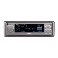
Car Receiver
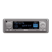
DEX-P9R
Service Manual
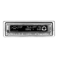
Page 30 (4 Pcb Connection Diagram)
Pioneer DEX-P9R - 4 Pcb Connection Diagram
96 pages
Manual
To Next Page
To Next Page
To Previous Page
To Previous Page
Loading...
OPT IN
IP-BUS IN
IP-BUS OUT
C
CN1201
F
M
FM/AM TUNER U
FRONT
D
CN173
M951
30
DEX-P9,P9R
A
1
234
B
C
D
12
34
4. PCB
4.1 AUDIO CONTROL PCB
A
A
AUDIO CONTROL PCB
Capacitor
Connector
P.C.Board
Chip Part
SIDE A
SIDE B
NOTE FOR PCB DIAGRAMS
1. The parts mounted on this PCB
include all necessary parts for
several destination.
For further information for
respective destinations, be sure
to check with the schematic
diagram.
2. Viewpoint of PCB diagrams
w
w
w
.
x
i
a
o
y
u
1
6
3
.
c
o
m
Q
Q
3
7
6
3
1
5
1
5
0
9
9
2
8
9
4
2
9
8
T
E
L
1
3
9
4
2
2
9
6
5
1
3
9
9
2
8
9
4
2
9
8
0
5
1
5
1
3
6
7
3
Q
Q
TEL 13942296513 QQ 376315150 892498299
TEL 13942296513 QQ 376315150 892498299
http://www.xiaoyu163.com
http://www.xiaoyu163.com
29
31
Table of Contents
Main Page
Default Chapter
1
Table of Contents
1
1 Safety Information
2
2 Exploded Views and Parts List
4
3 Block Diagram and Schematic Diagram
14
4 Pcb Connection Diagram
30
5 Electrical Parts List
42
6 Adjustment
56
Checking the Grating after Changing the Pickup Unit
58
7 General Information
60
Diagnosis
60
Test Mode
60
Disassembly
64
Connector Function Description
69
Operational Flow Chart
88
8 Operations and Specifications
89
Specifications
95
Other manuals for Pioneer DEX-P9R
Owner's Manual
96 pages
Related product manuals
Pioneer DEX-P9
96 pages
Pioneer DEX-P99R
107 pages
Pioneer dex-p99rs
77 pages
Pioneer DEX-P90RS
94 pages
Pioneer DEX-P1
142 pages
Pioneer DEX-P1R
142 pages
Pioneer DEH-6
68 pages
Pioneer DEH-11
56 pages
Pioneer DEH-X5
50 pages
Pioneer DEH-230
61 pages
Pioneer DEH-345
84 pages
Pioneer DEH-P41
92 pages
 Loading...