EasyManua.ls Logo

Pioneer DT-500 Service Manual

Pioneer DT-500
12 pages
To Next Page IconTo Next Page
Page #1 background imageLoading...
Page #1 background image
REcEtyED
nAR
I
s
Bsg
Bll'l
-ta*rlrcl
f
AUDIO
DIGITAL
TIMER
DTI
5OO
MODEL
DT-SOO
COMES
IN
SIX
VERSIONS
DISTINGUISHED
AS
FOLLOWS:
r
This
service manual
is
applicable
to the DT-500/S,S/G.
When
repairing
the DT-500/KU,
please
see
page
11,
and
for
the
other types,
please
refer
to the
additional
service
manuals.
CONTENTS
1.
SPECIFICATIONS
2
2. PARTS
LOCATIONS
2
3.FRONTPANELFACILITIES
....3
4.EXPLODEDVIEW
.....4
5.
SCHEMATICDIAGRAMS....
........
5
6.
P.C.BOARDCONNECTIONDIAGRAM,.
.. ....
7
7.
PARTS
LIST
.
9
S.PACK|NG
......10
ADDITIONAL
SERVICE
MANUAL
(For
KU modet)
1 .
SPECIF ICATTONS
11
2. CONTRAST OF M ISCELLANEOUS
PARTS
11
3.PARTSLTST.
.......12
4. SCHEMATICD|AGRAMS....
....... 13
5.
P.C.
BOARD PATTERNS
15
Type
Voltage
Remarks
KU
120V
only
U.S.A. model
KC
120V only
Canada
model
S
1 10V,
12OV,
22OV
and 240V
(switchabte)
General
export
model
S/G
110V,
120V,
220V
and 240V
(Switchabte)
U.S. Military
model
YB
240V
only
United
Kingdom
model
NE
22OV only
Europe
model
PICINEEFI ELECTFICINIC
CCIFIPOFIATICIN
4-1. Mesuno
'1
-chome,
Mesuno-ku, Tokyo
153, Japan
U.B. PIONEEFI ELECTFICINICA
COFIPOFIATION
85 Oxfond Dnrve, Moonach
e,
New
Jeesey O7O74, U.S.A.
PICINEEFI
ELECTFICINIC
(EUFICIPE!
N.V. Lurthagen-Haven
9, 2O3O
Antwenp,
Belgrum
PIONEEFI
ELECTFICINICB
AUATFIALIA FTY.
L?El, 178-1A4 Boundany
Foad, Bnaesrde. Vrcto.ra 3195, Austnalra
<ART-564-0>
FU
O
l\4AY
1980
Printed
in
Japan
Question and Answer IconNeed help?

Do you have a question about the Pioneer DT-500 and is the answer not in the manual?

Pioneer DT-500 Specifications

General IconGeneral
BrandPioneer
ModelDT-500
CategoryTimer
LanguageEnglish

Summary

Pioneer DT-500 Service Manual

DT-500 Product Overview

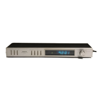
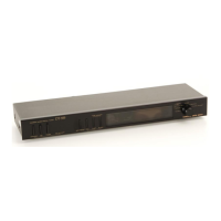
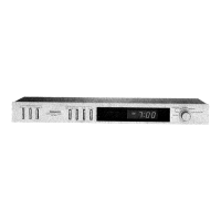
Introduction to the Pioneer DT-500 Audio Digital Timer.

DT-500 Model Variations

Details on the six versions of the DT-500 model (KU, KC, S, S/G, YB, NE).

DT-500 Front Panel Controls and Features

AC Outlet Selector Operation

Explains the function of the AC outlet selector (OFF/ON/TIMER).

Time Setting Adjustment Switches

Details on using SEC RESET, FAST, SLOW, and REV switches.

Mode Selector Operation

Describes the functions of the SLEEP, TIMER SET, CLOCK, SECOND modes.

DT-500 Exploded View and Parts List

Exploded View Diagram

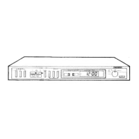
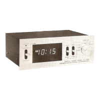
Visual layout of the unit's components with numbered parts.

DT-500 Schematic Diagrams

Main Circuit Diagram

The primary electronic circuit schematic for the DT-500.

DT-500 PCB Connection Diagrams

Voltage Selector and Transformer Wiring

Diagram showing power input, voltage selection, and transformer connections.

MN6076 IC Block Diagram

Explains the internal functional blocks of the MN6076 integrated circuit.

DT-500 KU Model Additional Manual

KU Model Specifications Overview

Specifications for the KU type, referencing S type sections.

DT-500 KU Model Schematic Diagrams

KU Model Main Circuit Diagram

The primary electronic circuit schematic for the KU model.

Related product manuals