EasyManua.ls Logo

Pioneer DV-380-S Service Manual

Pioneer DV-380-S
86 pages
To Next Page IconTo Next Page
Page #1 background imageLoading...
Page #1 background image
ORDER NO.
PIONEER CORPORATION 4-1, Meguro 1-chome, Meguro-ku, Tokyo 153-8654, Japan
PIONEER ELECTRONICS (USA) INC. P.O. Box 1760, Long Beach, CA 90801-1760, U.S.A.
PIONEER EUROPE NV Haven 1087, Keetberglaan 1, 9120 Melsele, Belgium
PIONEER ELECTRONICS ASIACENTRE PTE. LTD. 253 Alexandra Road, #04-01, Singapore 159936
PIONEER CORPORATION 2005
RRV3156
T – ZZR APR. 2005 Printed in Japan
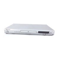
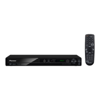
DVD PLAYER
DV-380-S
This service manual should be used together with the following manual(s):
Model No. Order No. Remarks
DV-380-S / WYXTL RRV3111
The voltage can be converted
by the following method.
Reginal restriction
codes (Region No.)
THIS MANUAL IS APPLICABLE TO THE FOLLOWING MODEL(S) AND TYPE(S).
Model
DV-380-S
Type
Power Requirement
WYXTL / UR
AC220-240V
DV-380-K
AC220-240V
Automatic select
Automatic select
5
5WYXTL / UR
DV-380-K
w
w
w
.
x
i
a
o
y
u
1
6
3
.
c
o
m
Q
Q
3
7
6
3
1
5
1
5
0
9
9
2
8
9
4
2
9
8
T
E
L
1
3
9
4
2
2
9
6
5
1
3
9
9
2
8
9
4
2
9
8
0
5
1
5
1
3
6
7
3
Q
Q
TEL 13942296513 QQ 376315150 892498299
http://www.xiaoyu163.com

Other manuals for Pioneer DV-380-S

Questions and Answers:

Pioneer DV-380-S Specifications

General IconGeneral
BrandPioneer
ModelDV-380-S
CategoryDVD Player
LanguageEnglish

Summary

SAFETY INFORMATION

[Important Check Points for Good Servicing]

1. Product safety

Outlines safety precautions for servicing, including parts, modifications, soldering, and environment.

2. Adjustments

Instructions for product adjustments to maintain performance and specifications.

1. SPECIFCATIONS

2. EXPLODED VIEWS AND PARTS LIST

2.3 05 DVD MECHA SECTION

3. BLOCK DIAGRAM AND SCHEMATIC DIAGRAM

3.1 BLOCK DIAGRAM

Shows the overall block diagram of the DVD player system.

3.2 OVERALL WIRING CONNECTION DIAGRAM

3.4 DVD MT PCB ASSY (2/5)

3.5 DVD MT PCB ASSY (3/5)

3.6 DVD MT PCB ASSY (4/5)

3.7 DVD MT PCB ASSY (5/5)

3.8 OPERATION 1 and OPERATION 2 PCB ASSYS

3.9 POWER PCB ASSY (1/2)

3.10 POWER PCB ASSY (2/2)

3.11 WAVE FORMS

4. PCB CONNECTION DIAGRAM

4.2 DVD MT PCB ASSY

4.3 OPERATION 1 and OPERATION 2 PCB ASSYS

4.4 POWER PCB ASSY

5. PCB PARTS LIST

6. ADJUSTMENT

DVD Deck Replacement Procedure

Procedures for removing and installing the DVD deck, including safety notes.

6.3 TEST MODE IN

6.4 DISC REMOVAL METHOD

Disc Removal Without Power

Procedures for removing a disc without power, including diagram.

Servicing Static Electricity Precautions

Essential precautions for servicing, especially regarding static electricity.

7.1.2 SHORTCUT KEY FUNCTIONS

7.1.3 MODEL INFORMATION DISPLAY SPECIFICATIONS

7.1.4 SERVICE MODE FUNCTIONAL SPECIFICATION

7.1.5 LASER DIODE DEGRADATION DIAGNOSIS

7.1.6 TROUBLE SHOOTING

Power, Display, and Mechanism Issues

Troubleshooting for power, display, disc tray, and playback mechanism problems.

Playback and Signal Issues

Troubleshooting for playback errors, picture disturbances, no sound, and signal output checks.

IC Failure Symptoms

7.2 DISASSEMBLY

Top Cabinet, Front Cabinet, and Operation PCBs Removal

Steps for removing top cabinet, front cabinet, and operation PCBs with diagrams.

Power PCB Removal Procedure

Steps for removing the power PCB, including connector and screw removal.

DVD Deck Removal Procedure

Procedures for removing the DVD deck, including connector disconnection and screw removal.

DVD PCB Removal Procedure

Steps for removing the DVD PCB, including screw removal.

Switch PCB, Gears, and Motors Removal

7.4 IC INFORMATION

MT1389FE IC Block Diagram

MT1389FE IC Pin Functions

LA6565 IC Details

LA6565 IC Block Diagram and Pin Functions

Covers the internal block diagram and pin functions for the LA6565 motor drive IC.

PT6315 IC Details

7.5 DISC COMPATIBILITY

8.3 REMOTE CONTROL

Related product manuals