Do you have a question about the Pioneer DV-45A and is the answer not in the manual?
General safety precautions for service technicians, including leakage current checks.
Highlights special safety characteristics of electrical components and replacement parts.
Conform to regulations and follow safety instructions during servicing.
Ensure optimum performance by performing adjustments and specification confirmation.
Proper cleaning for optical pickups, heads, lenses, and mirrors to restore performance.
Set shipping mode or install shipping screws to protect the product during transit.
Proper application of lubricants/glue and use of prescribed replacement parts/tools.
Details general specifications including power, dimensions, and operating conditions.
Details specifications for component, S-Video, and standard video outputs.
Details specifications for stereo and multi-channel audio outputs.
Specifications for digital audio characteristics and digital output types.
Lists included accessories like cables, remote control, batteries, and manuals.
Illustrates the packing configuration of the product components.
Lists parts included in the packing, referencing contrast tables.
Compares parts and specifications for DV-45A/KUXJ/CA and DV-656A/KUXJ/CA models.
Lists all parts associated with the exterior section, referencing contrast tables.
Compares parts and specifications for DV-45A/KUXJ/CA and DV-656A/KUXJ/CA models.
Details the components and layout of the tray panel section for different models.
Lists all parts associated with the front panel section.
Compares parts and specifications for DV-45A/KUXJ/CA and DV-656A/KUXJ/CA models.
Lists all parts associated with the loading mecha assembly.
Lists all parts associated with the traverse mechanism assembly.
High-level block diagram showing the signal flow and main functional units.
Wiring diagram showing connections between LOAB, SACDB, JACB, and DVDM assemblies.
Schematic diagram for the DVDM Assy, showing internal connections and components.
Schematics for FLKY Assy and Power Supply Unit, detailing their circuitry.
Schematics for Pickup Assy-S and Loading Motor Assy, showing internal configurations.
Schematic and pin functions for the DVDM Assy FTS block.
Schematic diagram for the DVDM Assy, focusing on VCO Circuit and SERVO DSP.
Schematic diagram for the DVDM Assy FR block, detailing the FR CPU connections.
Schematic diagram for the DVDM Assy, showing the M65776AFP and other components.
Schematic diagram for the DVDM Assy EBY/AV1 block, detailing the EBY-CHIP.
Schematic diagram for the DVDM Assy, showing the M65776AFP MPEG, DVD-Audio, DTS Decoder.
Schematic diagram for the DVDM Assy VENC block, showing the ADV7172KST Video Encoder.
Schematic diagram for the JACB Assy audio block.
Schematic diagram for the JACB Assy, showing audio amplifier circuits.
Schematic diagram for the JACB Assy video block.
Schematics for CVBS, Video Out, and Component Video Out.
Schematic diagram for the SACDB Assy, showing AUDIO DSP connections.
Schematic diagram for the CXD2753R SACD Decoder IC.
Schematic diagram for the FLKY Assy, detailing its components and connections.
Schematic diagram for the KEYB Assy, detailing its components and connections.
Schematics for FLKY and KEYB assemblies, detailing components and pin functions.
Illustrates various waveforms from the DVDM Assy, with measurement conditions.
Illustrates various waveforms from the JACB Assy, with measurement conditions.
Shows PCB connection layouts and part number comparisons for the LOAB Assy.
Top views of the JACB Assy PCB (Sides A & B), showing component placement and labels.
Top views of the SACDB Assy PCB (Sides A & B), showing component placement and labels.
Top views of the FLKY and KEYB Assy PCBs, showing component placement and functions.
Lists part numbers for assemblies, semiconductors, coils, filters, capacitors, resistors, and others.
Lists semiconductors, coils, capacitors, resistors, and others for the DVDM Assy [VWS1531].
Identifies adjustment items and their locations on the mechanism and electrical parts.
Lists necessary jigs and measuring instruments for adjustments.
Instructions for entering, setting discs, playing, and exiting test mode.
Procedure for adjusting tangential and radial height using screws and spacers.
Covers diagnostic procedures, including ID setting and self-diagnosis.
Procedure to enter and set the player's ID number and ID data.
Steps to confirm the currently set ID number on the player.
Procedure to clear the player's ID number and reset settings.
Steps to perform self-diagnosis for pickup defects, checking laser diode current.
Explanation of the test mode screen display elements and their meanings.
Displays mechanism error history and self-diagnosis results for troubleshooting.
Details AGC settings, FTS servo IC info, and error rate indicators (CD/DVD).
Shows the internal operation mode and step of the mechanism controller.
Details the past eight errors recorded for the mechanism controller.
Lists items checked during self-diagnosis, including AV1 Host Bus, Bus, DMA, Video encoder, DSP, SACD, 1394.
Explains FL display indications for EDC/ID errors and how to release them.
Details the service mode screen display, including error rate, self-diagnosis, and AV decoder error info.
Lists error codes displayed on the FL display and their corresponding causes and operations.
Lists error codes displayed via remote control and their causes/operations for DVD and CD.
Identifies test points on Side A and Side B of the DVDM Assy.
Illustrates various waveforms from the DVDM Assy, with measurement conditions.
Troubleshooting steps for PCB issues, including checking connections and voltages.
Steps for disassembling the bonnet, tray panel, and front panel.
Procedure for removing the DVDM Assy from the unit.
Method to diagnose audio signals of DVDM Assy without SACDB Assy.
Observe signal waveforms on CN902 of SACDB Assy to confirm SACD/DSP block function.
Steps for removing screws, short switch, flexible cables, and connector from the loading mecha.
Procedure for removing and inserting the tray, including caution for alignment.
Steps for removing FFC holder, pickup flexible cable, and traverse mechanism assembly.
Procedure for removing the pickup assembly, including screws and springs.
Lists integrated circuits used in the DVDM Assy, with their part numbers.
Block diagram and pin functions for the LA9704W RF IC.
Details pin functions for various ICs like TS, TES, BCK, VCC, etc.
Block diagram of the LC78652W Servo DSP IC, showing its internal processing blocks.
Block diagram of the BAG6664FM Three-phase Motor Driver IC.
Block diagram and pin functions for the PD6345A FR CPU IC.
Block diagram of the M65776AFP MPEG2 Decoder IC.
Block diagram of the AD7172KST Video Encoder IC.
Block diagram of the PCM1738EG-3 D/A Converter IC.
Block diagram of the LA73054 DVD Video Amplifier IC.
Pin arrangement diagram for the CXD2753R SACD Decoder IC.
Lists compatible disc types like DVD-Audio, DVD-Video, CD Audio, etc.
Details compatibility for CD-R/RW and DVD-R/RW discs, including playback and recording limitations.
Lists other formats like Photo CD, DVD-ROM, and CD-ROM that are not playable.
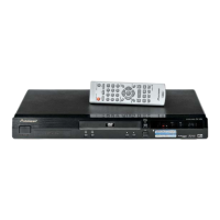
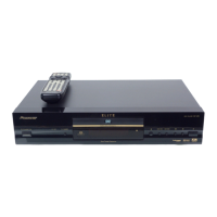
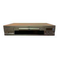
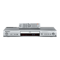
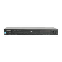
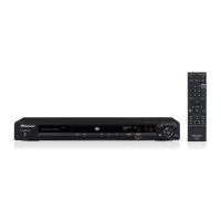
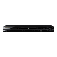
Description of the front panel controls, buttons, indicators, and display.
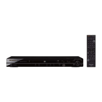
Explains the functions of the buttons on the DV-45A remote control.
Explains the functions of the buttons on the DV-656A remote control.
| Type | DVD Player |
|---|---|
| Progressive Scan | Yes |
| Audio DAC | 192 kHz/24-bit |
| Video Output | Composite, S-Video, Component |
| Signal-To-Noise Ratio | 115 dB |
| Dynamic Range | 100 dB |
| Output Resolution | 480p, 720p, 1080i |
| Disc Formats | DVD-Video, CD, CD-R/RW |
| Audio Output | Stereo Analog, Coaxial Digital, Optical Digital |
| Weight | 3.8 kg |
| Frequency Response | 4 Hz - 44 kHz (DVD) |