EasyManua.ls Logo

Pioneer DV-454-K User Manual

Pioneer DV-454-K
102 pages
To Next Page IconTo Next Page
Page #1 background imageLoading...
Page #1 background image
ORDER NO.
PIONEER CORPORATION 4-1, Meguro 1-chome, Meguro-ku, Tokyo 153-8654, Japan
PIONEER ELECTRONICS (USA) INC. P.O. Box 1760, Long Beach, CA 90801-1760, U.S.A.
PIONEER EUROPE NV Haven 1087, Keetberglaan 1, 9120 Melsele, Belgium
PIONEER ELECTRONICS ASIACENTRE PTE. LTD. 253 Alexandra Road, #04-01, Singapore 159936
PIONEER CORPORATION 2002
RRV2610
T – ZZE MAY 2002 Printed in Japan
For details, refer to "Important symbols for good services".
DVD PLAYER
DV-454-K
DV-454-S
THIS MANUAL IS APPLICABLE TO THE FOLLOWING MODEL(S) AND TYPE(S).
Model Power Requirement
Regional restriction
codes (Region No.)
Remarks
DV-454-K AC220-240V 2
DV-454-S
DV-454-S
DV-454-S
AC220-240V 2
Type
WYXU
WYXU/FRGR
WVXU
WYXU
WYXU/FRGR
WVXU
AC220-240V
AC220-240V
2
2
STANDBY/ON
Î
3
OPEN/
CLOSE
0
8
7
1
4
¡
¢
DV-454-K
Serial No.
Confirm it
Question and Answer IconNeed help?

Do you have a question about the Pioneer DV-454-K and is the answer not in the manual?

Pioneer DV-454-K Specifications

General IconGeneral
BrandPioneer
ModelDV-454-K
CategoryDVD Player
LanguageEnglish

Summary

SAFETY INFORMATION

SPECIFICATIONS

EXPLODED VIEWS AND PARTS LIST

2.1 PACKING

Lists items included in the product packaging.

2.2 EXTERIOR SECTION

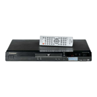
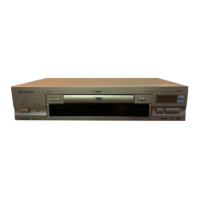
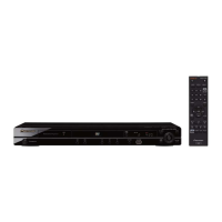
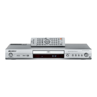
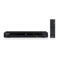
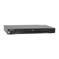
Shows the external components and their locations on the unit.

2.3 LOADING MECHANISM ASSY

Exploded view and parts list for the disc loading mechanism.

2.4 TRAVERSE MECHANISM ASSY-S

Exploded view and parts list for the disc traverse mechanism.

BLOCK DIAGRAM AND SCHEMATIC DIAGRAM

3.1 BLOCK DIAGRAM

Overall system block diagram illustrating signal flow.

3.1.2 POWER SUPPLY BLOCK

Schematic showing the power supply distribution within the unit.

3.1.3 WAVEFORMS

Displays oscilloscope waveforms for key test points.

3.2 LOAB ASSY and OVERALL WIRING DIAGRAM

Wiring diagram for the LOAB assembly and overall connectivity.

3.3 FJMB ASSY 1/5 [FRONT END BLOCK]

Schematic of the FJMB assembly's front end section.

3.4 FJMB ASSY 2/5 [BACK END BLOCK]

Schematic of the FJMB assembly's back end section.

3.5 FJMB ASSY 3/5 [AUDIO BLOCK]

Schematic of the FJMB assembly's audio processing block.

3.6 FJMB ASSY 4/5 [VIDEO BLOCK]

Schematic of the FJMB assembly's video processing block.

3.7 FJMB ASSY 5/5 [FL CONTROL BLOCK]

Schematic of the FJMB assembly's front panel control block.

3.8 IRKY and PSWB ASSYS

Schematics for IRKY and PSWB assemblies.

3.9 POWER SUPPLY UNIT (VWR1352)

Schematic of the VWR1352 power supply unit.

3.10 POWER SUPPLY UNIT (VWR1354)

Schematic of the VWR1354 power supply unit.

3.11 SCRB ASSY

Schematic of the SCRB assembly.

PCB CONNECTION DIAGRAM

4.1 LOAB ASSY

PCB layout and connection points for the LOAB assembly.

4.2 FJMB ASSY

PCB layout for the FJMB assembly.

4.3 IRKY and PSWB ASSYS

PCB layouts for IRKY and PSWB assemblies.

4.4 POWER SUPPLY UNIT (VWR1352)

PCB layout for the VWR1352 power supply unit.

4.5 POWER SUPPLY UNIT (VWR1354)

PCB layout for the VWR1354 power supply unit.

4.6 SCRB ASSY

PCB layouts for the SCRB assembly.

PCB PARTS LIST

ADJUSTMENT

6.1 ADJUSTMENT ITEMS AND LOCATION

Lists adjustment points and their locations on the mechanism.

6.2 JIGS AND MEASURING INSTRUMENTS

Lists necessary tools for performing adjustments.

6.3 NECESSARY ADJUSTMENT POINTS

Specifies adjustment procedures based on part replacement.

6.4 TEST MODE

Instructions for entering and operating the device's test mode.

6.5 MECHANISM ADJUSTMENT

Details on performing coarse adjustments for mechanism parts.

GENERAL INFORMATION

7.1 DIAGNOSIS

General diagnostic procedures and information.

7.1.1 TEST MODE

Functional specifications for various test modes.

7.1.2 DISPLAY OF THE MECHANISM ERROR HISTORY

How to interpret mechanism error codes and states.

7.1.3 TEST POINT LOCATION & WAVEFORMS

Identifies test points and provides waveform examples.

7.1.4 TROUBLE SHOOTING

Symptom-based troubleshooting guide.

7.1.5 SEQUENCE AFTER THE POWER ON

Flowchart illustrating power-on sequence.

7.1.6 DISASSEMBLY

Step-by-step instructions for disassembling major assemblies.

7.2 IC

Lists and describes key integrated circuits used in the unit.

7.3 CLEANING

Procedures for cleaning key components before shipping.

PANEL FACILITIES

Front panel

Identifies controls and indicators on the front panel.

Rear panel connections

Describes the function of each connector on the rear panel.

Related product manuals