EasyManua.ls Logo

Pioneer DVH-730AV User Manual

Pioneer DVH-730AV
84 pages
To Next Page IconTo Next Page
Page #1 background imageLoading...
Page #1 background image
PIONEER CORPORATION 1-1, Shin-ogura, Saiwai-ku, Kawasaki-shi, Kanagawa 212-0031, Japan
PIONEER ELECTRONICS (USA) INC. P.O. Box 1760, Long Beach, CA 90801-1760, U.S.A.
PIONEER EUROPE NV Haven 1087, Keetberglaan 1, 9120 Melsele, Belgium
PIONEER ELECTRONICS ASIACENTRE PTE. LTD. 253 Alexandra Road, #04-01, Singapore 159936
PIONEER CORPORATION 2011
DVH-730AV/XZUW5
CRT4714P
DVD AV RECEIVER
DVH-730AV
/XZUW5
DVH-735AV/XZRD
DVH-735AV/XZRI
DVH-7380AV/XFBR
For details, refer to "Important Check Points for Good Servicing".
K-ZZZ JULY 2011 Printed in Japan
PROVISIONAL
Question and Answer IconNeed help?

Do you have a question about the Pioneer DVH-730AV and is the answer not in the manual?

Pioneer DVH-730AV Specifications

General IconGeneral
Display TypeLCD
Max Power Output50 W x 4
Audio Formats SupportedMP3, WMA, AAC
BluetoothYes
USB PortYes
Preamp Outputs3 (Front, Rear, Subwoofer)
Equalizer13-band graphic equalizer
AUX InputYes
Video OutputYes
Remote ControlYes
Video Formats SupportedMPEG-1, MPEG-2, MPEG-4
Playback FormatsCD, DVD, USB
Media CompatibilityCD, USB, Bluetooth

Summary

1. SERVICE PRECAUTIONS

1.1 SERVICE PRECAUTIONS

General safety guidelines for qualified service technicians.

1.2 NOTES ON SOLDERING

Precautions for using lead-free solder and soldering iron settings.

2. SPECIFICATIONS

2.1 SPECIFICATIONS

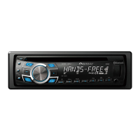
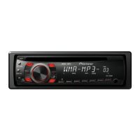
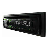
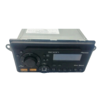
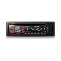
Detailed technical specifications for the DVH-730AV/XZUW5 model.

2.2 DISC/CONTENT FORMAT

3. BASIC ITEMS FOR SERVICE

3.1 CHECK POINTS AFTER SERVICING

Procedures to confirm product quality and customer issue resolution after service.

3.2 PCB LOCATIONS

3.3 JIGS LIST

3.4 CLEANING

4. BLOCK DIAGRAM

4.1 BLOCK DIAGRAM

Overall system block diagram illustrating component interconnections.

4.2 POWER BLOCK DIAGRAM

5. DIAGNOSIS

5.1 OPERATIONAL FLOWCHART

Step-by-step flowchart for diagnosing power-on operation.

5.2 ERROR CODE LIST

5.3 CONNECTOR FUNCTION DESCRIPTION

6. SERVICE MODE

6.1 SOFTWARE VERSION INFORMATION DISPLAY

Instructions to display software version information using the remote control.

7. DISASSEMBLY

Removing the Case

Steps to remove the top and bottom case of the unit.

Removing the Mechanism

Procedure to remove the DVD mechanism module.

Removing the Panel Assy

Steps to disconnect cables and remove the panel assembly.

Removing the Mother Unit

How to eject the stuck disc (Procedure 1: Rotating the roller)

How to eject the stuck disc (Procedure 2: Removing the top cover)

8. EACH SETTING AND ADJUSTMENT

9. EXPLODED VIEWS AND PARTS LIST

9.1 PACKING

Exploded view and parts list for the product's packing.

9.2 EXTERIOR (1)

9.3 EXTERIOR (2)

9.4 MECHANISM

10. SCHEMATIC DIAGRAM

10.1 MOTHER UNIT (1/2) (GUIDE PAGE)

Schematic diagram for the first half of the Mother Unit.

10.2 MOTHER UNIT (2/2) (GUIDE PAGE)

10.3 DVD DECODE UNIT (POWER PART) (GUIDE PAGE)

10.4 DVD DECODE UNIT (MAIN PART) (GUIDE PAGE)

10.5 KEYBOARD PCB and AUX PCB (GUIDE PAGE)

10.6 LB PCB and CB PCB

10.7 KB-SB PCB

11. PCB CONNECTION DIAGRAM

11.1 MOTHER UNIT CONNECTION DIAGRAM

Connection diagram for the Mother Unit's PCBs.

11.2 DVD DECODE UNIT

11.3 KEYBOARD PCB

11.4 AUX PCB

11.5 LB PCB

11.6 KB-SB PCB

12. ELECTRICAL PARTS LIST

MISCELLANEOUS ELECTRICAL PARTS

List of miscellaneous electrical components like ICs, transistors, and FETs.

KB Assy Parts List

Parts list for the Keyboard Assembly.

CB Assy Parts List

Parts list for the CB Assembly.

Mother Unit Parts List

Parts list for the Mother Unit.

DVD Decode Unit Parts List

Parts list for the DVD Decode Unit.

Related product manuals