Do you have a question about the Pioneer DVH-7380AV/XFBR and is the answer not in the manual?
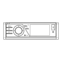
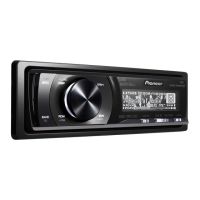
| Screen Size | 6.2 inches |
|---|---|
| Resolution | 800 x 480 pixels |
| Max Power Output | 50W x 4 |
| Audio Formats Supported | MP3, WMA, AAC |
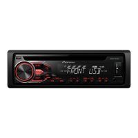
| Bluetooth | Yes |
| USB Port | Yes |
| Aux Input | Yes |
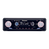
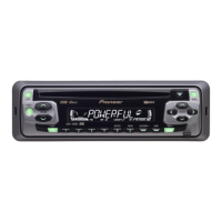
| DVD Player | Yes |
| CD Playback | Yes |
| AM/FM Tuner | Yes |
| Rear View Camera Input | Yes |
| Steering Wheel Control | Yes |
| Video Output | Yes |
| Preamp Outputs | 3 (Front, Rear, Subwoofer) |
| Display Type | LCD |
| Video Formats Supported | MPEG-1, MPEG-2 |
General safety guidelines for technicians, including handling precautions.
Warnings regarding laser radiation exposure and battery replacement hazards.
Adherence to regulations and handling precautions during servicing.
Best practices for lead-free soldering and component handling.
Procedures to confirm product quality and functionality after repair.
Overview of the unit's functional blocks and interconnections.
Detailed breakdown of the unit's power supply system and current distribution.
Common error messages, their causes, and recommended actions.
Step-by-step guide for removing the outer case and internal mechanism.
Steps for disconnecting and removing the main circuit board.
Method to eject a stuck disc by manual roller manipulation.
Alternative method to eject a stuck disc by partial disassembly.
Circuit diagram for the primary motherboard section.
Circuit diagram for the secondary motherboard section.
Circuit diagram for the power section of the DVD decode unit.
Circuit diagram for the main section of the DVD decode unit.
Circuit diagrams for keyboard and auxiliary input PCBs.