EasyManua.ls Logo

Pioneer DVH-735AV/XZRD User Manual

Pioneer DVH-735AV/XZRD
84 pages
To Next Page IconTo Next Page
Page #1 background imageLoading...
Page #1 background image
PIONEER CORPORATION 1-1, Shin-ogura, Saiwai-ku, Kawasaki-shi, Kanagawa 212-0031, Japan
PIONEER ELECTRONICS (USA) INC. P.O. Box 1760, Long Beach, CA 90801-1760, U.S.A.
PIONEER EUROPE NV Haven 1087, Keetberglaan 1, 9120 Melsele, Belgium
PIONEER ELECTRONICS ASIACENTRE PTE. LTD. 253 Alexandra Road, #04-01, Singapore 159936
PIONEER CORPORATION 2011
DVH-730AV/XZUW5
CRT4714P
DVD AV RECEIVER
DVH-730AV
/XZUW5
DVH-735AV/XZRD
DVH-735AV/XZRI
DVH-7380AV/XFBR
For details, refer to "Important Check Points for Good Servicing".
K-ZZZ JULY 2011 Printed in Japan
PROVISIONAL
Question and Answer IconNeed help?

Do you have a question about the Pioneer DVH-735AV/XZRD and is the answer not in the manual?

Pioneer DVH-735AV/XZRD Specifications

General IconGeneral
Audio Output Power50W x 4
Tuner TypeFM/AM
BluetoothYes
USB PortYes
Aux InputYes
Preamp Outputs3 (Front, Rear, Subwoofer)
DVD PlayerYes
Rear Camera InputYes
Video OutputYes
CD PlaybackYes
Display TypeLCD
Screen Size6.2 inches
Resolution800 x 480
Supported FormatsMP3, WMA, WAV
Steering Wheel ControlYes

Summary

Pioneer Service Manual

Model DVH-730AV/XZUW5 Identification

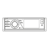
Identifies the specific Pioneer model covered by this service manual.

Safety Information

General Safety Precautions for Technicians

General safety rules and warnings for qualified service technicians.

Laser Diode Safety Precautions

Precautions when checking laser diode emitting power, distance, and viewing.

Radiation Exposure Warning

Caution regarding hazardous radiation exposure from controls or optical instruments.

Laser Product Warning

Warning not to remove covers due to internal laser diode.

Battery Safety

Caution about explosion risk if battery is replaced incorrectly.

Service Precautions

General Service Precautions

Guidelines for adhering to product regulations and safety during servicing.

Notes on Soldering

Guidelines for using lead-free solder and soldering irons for repairs.

Specifications

Basic Service Items

Post-Service Checks and Procedures

Confirms product quality, complaint resolution, and lists specific check items for image/voice.

Block Diagrams

Overall System Block Diagram

Illustrates the interconnections between major functional units of the system.

Power Block Diagram

Diagnosis and Troubleshooting

Error Code List

Error Messages, Causes, and Actions

Details error messages displayed, their causes, and recommended corrective actions.

Connector Function Descriptions

Disassembly Procedures

Mother Unit Disassembly

Stuck Disc Ejection Procedure 1

Rotating the Roller Mechanism for Ejection

Steps involving cover removal and roller mechanism manipulation to eject a stuck disc.

Stuck Disc Ejection Procedure 2

Top Cover and Dustproof Cover Removal

Steps to remove the top and dustproof covers to access and eject a stuck disc.

Exploded Views and Parts Lists

Schematic Diagrams: Mother Unit Part 1

Mother Unit (1/2) Circuit Diagram

Circuit diagram for the first half of the Mother Unit, detailing its electrical connections.

Schematic Diagrams: Mother Unit Part 2

Mother Unit (2/2) Circuit Diagram

Circuit diagram for the second half of the Mother Unit, covering audio and video circuitry.

Schematic Diagrams: DVD Decode Unit Power Part

DVD Decode Unit (Power Part) Circuit Diagram

Circuit diagram for the power supply and DC-DC conversion sections of the DVD decode unit.

Schematic Diagrams: DVD Decode Unit Main Part

DVD Decode Unit (Main Part) Circuit Diagram

Circuit diagram for the main processing and memory sections of the DVD decode unit.

Schematic Diagrams: Keyboard and AUX PCBs

PCB Connection Diagrams

DVD Decode Unit PCB Diagram - Side A

DVD Decode Unit PCB Diagram - Side B

Keyboard PCB Connection Diagrams

Keyboard PCB Connection Diagrams - Side B

Electrical Parts List

Related product manuals