Do you have a question about the Pioneer DVL-919E and is the answer not in the manual?
Compares PCB assemblies and lists associated parts for different models.
Details packing components and operating instructions for various models.
Lists components for physical sections like front panel, top, and bottom views.
Lists various capacitors, coils, and filters with part numbers.
Lists resistors and other miscellaneous electronic components.
Schematic diagram for the CLDM assembly, part 2 of 3.
PCB connection layout for the CLDM assembly.
| Type | DVD Player / LaserDisc Player |
|---|---|
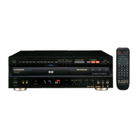
| Remote Control | Yes |
| Signal-to-Noise Ratio | 115 dB |
| Frequency Response | 4 Hz - 22 kHz |
| Video Formats Supported | DVD, LaserDisc |
| Audio Formats Supported | Dolby Digital, DTS, PCM |
| Output Connections | Composite Video, S-Video, Component Video |
| Laser Wavelength | 650 nm (DVD) |