Do you have a question about the Pioneer DVR-555HX-S and is the answer not in the manual?
Table detailing differences in PCB assemblies, packing, and exterior/front panel sections.
Warning about laser radiation exceeding CLASS 1 limits and requiring trained personnel.
Conforming to product regulations and maintaining a safe servicing environment.
Procedures for maintaining original performance through optimum adjustments.
Notes on using lead-free solder, soldering iron tip temperature, and lead-free solder types.
Sensitivity to shock, electrostatic charges, and temperature changes affecting HDD.
Safety environment and handling procedures for the HDD as a repair part, including antistatic measures.
Measures to be taken when replacing SDRAM, depending on the manufacturer (ELPIDA or SAMSUNG).
Step-by-step procedure for replacing the FL Lens, ensuring proper alignment and attachment.
List of accessories supplied with the DVR-LX60D/WYXK5 and DVR-550HX-S/WYXK5.
General specifications like power requirements, consumption, weight, dimensions, and operating conditions.
Estimated recording times for HDD and various DVD disc types and modes.
Detailed specifications for various input and output connections, including antenna, video, audio, and USB.
Explanations for the marks and notes used in the disc/content format table.
Compatibility details for CD-R/-RW discs, including readable formats and multi-session playback.
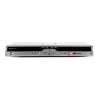
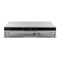
Identification and description of each connector and terminal on the rear panel.
Procedure for inserting a CA module into the Common Interface card slot.
Indicators for recording quality modes such as XP, SP, LP/SLP, EP/SEP, and MN.
Explanation of the service mode's utility for checking product status and gathering failure diagnosis information.
To check system control computer, tuner microcomputer, drive firmware versions, and RF level.
Procedure for displaying writer maintenance information, including error logs and LD emission duration.
Explanation of VR-recording-related errors displayed on the lines "Rec Err.".
Provides details on VR-playback errors, including display position and error message logs.
To check communication between a DV device and the unit when connected normally.
Lists potential causes for DV input, picture, sound, and recording problems.
To infer malfunctions by checking conditions for obtaining past EPG data, such as data absence or missing data.
Purpose of the first HDMI service mode screen, which displays connection status and resolution.
Description of items displayed on the HDMI main information screen, referring to subsequent tables for details.
To reproduce recording/playback symptoms that are difficult to reproduce under normal conditions.
Instructions on how to enter Aging Mode by switching to DVD or HDD and pressing specific remote control keys.
To check the operation of USB ports by connecting them, allowing for loop connection.
Procedure for checking the FL display indication and performing a detachment/attachment test.
Flowchart illustrating the steps for HDD diagnosis, including checking HDD information, self-tests, and read/write checks.
Lists common symptoms of HDD failure, such as errors, recording/playback issues, and non-recognition.
Details displayed for HDD information, such as model name, power-on time, and authentication status.
Description of the simplified HDD self-test for detecting serious failures.
Description of the extended self-test for reading all sectors of the HDD, with time requirements.
Description of the HDD read/write check, including data erasure and time requirements.
Lists the tests available in the diagnostic program: HDD Information, S.M.A.R.T. DST, and HDD R/W Check.
Detailed explanation of the HDD information fields: Model, Recog. No, and SMART threshold.
Explains how to interpret the results of the Self-Test, indicating completion or errors.
Explains how to interpret Extended Self-Test results, indicating normal operation or potential HDD replacement.
Detailed explanation of items displayed during the HDD R/W Check, such as write/read errors and progress.
Interpretation of diagnosis results, indicating HDD condition and replacement needs.
Procedure for removing the bonnet by unscrewing and removing five screws.
Procedure for opening and closing the tray panel using power and open/close buttons.
Method for opening the tray using an emergency disc ejection rod when the unit cannot be powered on.
Procedure for removing binders, screws, and the cord holder to access the writer stay.
Procedure for removing the low case U11 and the loader assembly.
Procedure for setting the model number, destination, and region number after replacing the MAIN Assy or TUJB Assy.
To ensure stable playback and recording by adjusting LD power when main board or PU is changed.
Explanation of adjustment modes: Drive Adjustment, PU Data Setting, and Power Adjustment.
Explains the time needed for each step mode, such as DVD Read Power and Disc Judgment.
Setting CPRM ID number and data for each recorder to ensure correct recording/playback of DVD-RW discs.
Notes on inputting the ID number while the unit is in Stop mode and the automatic unloading of the data disc.
Updating firmware to match system control computer, drive, and TUFL microcomputer versions, or to resolve symptoms.
Step-by-step procedure for updating firmware using a disc, including FL display indications.
Step-by-step procedure for serial firmware update using a PC and specific software.
Explanation of Specific-Channel Setting Mode for adjusting up to 12 channels individually.
Instructions on how to enter Specific-Channel Setting Mode by selecting a channel and pressing specific keys.
Tips on general setting mode, including its availability during recording/playback stop and input selection.
Exploded view of the packing section, showing all the parts included in the product packaging.
Note regarding cleaning paper usage and contact side identification.
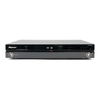
Exploded view of the front panel section for DVR-LX60D and DVR-LX60D-AV models.
Schematic diagram of the TUSB Assy, showing connections and component details.
Schematic diagram of the TUSB Assy, showing connections and component details.
Waveform diagrams for TUSB Assy test points, illustrating signals during DVD play and tuner operation.
Notes on matching part numbers in PCB diagrams with schematics and checking respective destinations.
List of major assemblies and their corresponding part numbers, including TUSB, DVUB, FLKB, FLKY, FRJB, DTVD, MAIN, and POWER SUPPLY.
List of miscellaneous components, including ICs, Fuses, Transistors, and Connectors, with their part numbers.
| Type | DVD Recorder |
|---|---|
| Hard Drive Capacity | 250 GB |
| Video Format | MPEG-2 |
| Audio Format | Dolby Digital, Linear PCM |
| Audio DAC | 24-bit / 192kHz |
| Video Recording Format | MPEG-2 |
| Recording Format | DVD-RAM, DVD-RW, DVD+RW, DVD-R, DVD+R |
| Connectivity | HDMI, Component Video, Composite Video, S-Video |
| Playback Formats | DVD-Video, MP3, JPEG |
| Disc Types | DVD-RAM, DVD-R, DVD-RW, DVD+R, DVD+RW, CD, CD-R, CD-RW |
| Playback Format | DVD-Video, DVD-RAM, DVD-RW, DVD+RW, DVD-R, DVD+R, CD, CD-R, CD-RW, MP3, JPEG |
| Output Resolution | 720p, 1080i |