Do you have a question about the Pioneer GM-X422 and is the answer not in the manual?
Service manual intended for qualified technicians; emphasizes safety and reliability concerns.
Warning about lead in solder and precautions for handling circuit boards and components.
Exploded view and parts list for the packing section of the amplifier.
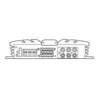
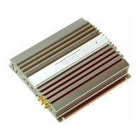
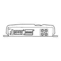
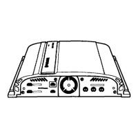
Exploded view illustrating the external components of the amplifier unit.
Schematic diagram for the Mother PCB, detailing component layout and connections.
Schematic diagram for the Isolator PCB, illustrating its circuit layout.
PCB connection diagram for the Mother PCB, showing component placement.
PCB connection diagram for the Isolator PCB, illustrating component layout.
List of miscellaneous electronic components including ICs, transistors, and passive parts.
Comprehensive list of resistors with circuit symbols, part names, and part numbers.
List of capacitors with circuit symbols, part names, and part numbers.
Step-by-step guide for disassembling the amplifier, including case and amp unit removal.
Guide for setting up and configuring the amplifier's operational features and controls.
Connection diagram specifically for the GM-X422/X1R/UC model.
Connection diagrams for GM-X422/X1R/ES and GM-X422/X1R/EW models.
Connection diagram for the GM-X322/X1R/UC model.
Instructions for connecting the power terminal of the amplifier to the vehicle's battery.
Instructions for connecting speaker wires to the amplifier's terminals.
Speaker wire connection modes for UC models, including two-channel and three-channel setups.
Speaker wire connection modes for ES models, covering two-channel and one-channel setups.
Speaker wire connection modes for EW models, covering two-channel and one-channel setups.