ORDER NO.
PIONEER CORPORATION 4-1, Meguro 1-chome, Meguro-ku, Tokyo 153-8654, Japan
PIONEER ELECTRONICS SERVICE, INC. P.O. Box 1760, Long Beach, CA 90801-1760, U.S.A.
PIONEER EUROPE NV Haven 1087, Keetberglaan 1, 9120 Melsele, Belgium
PIONEER ELECTRONICS ASIACENTRE PTE. LTD. 253 Alexandra Road, #04-01, Singapore 159936
PIONEER CORPORATION 2000
Model No. Order No. Remarks
M-F10/MYXJ RRV2321
STEREO POWER AMPLIFIER
RRV2397
T–ZZA OCT. 2000 Printed in Japan
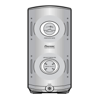
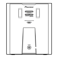
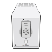
M-NS1
¶ This product is a system(s) component.
This product does not function properly independently ; to avoid malfunctions, be
sure to connect it to the prescribed system component(s), otherwise damage may
result.
¶ Please connect it to the STEREO CD/VCD TUNER XC-NS3V for adjustment and
operation inspection.
Component Model Service manual Remarks
STEREO CD/VCD TUNER XC-NS3V RRV2395 (RRV2381)
STEREO POWER AMPLIFIER M-NS1 RRV2397 (RRV2321) This manual.
SPEAKER SYSTEM S-NS1-LRW RRV2371
DBD/DF AC110–127V/220–230V/240V With the voltage selector
THIS MANUAL IS APPLICABLE TO THE FOLLOWING MODEL(S) AND TYPE(S).
The voltage can be converted by the following method.Power RequirementType
Model
M-NS1
MINIDISC RECORDER MJ-NS1 RRV2399 (RRV2363)
¶ This service manual should be used together with the following manual(s).