EasyManua.ls Logo

Pioneer M-LA21 User Manual

Pioneer M-LA21
24 pages
To Next Page IconTo Next Page
Page #1 background imageLoading...
Page #1 background image
ORDER NO.
PIONEER CORPORATION 4-1, Meguro 1-chome, Meguro-ku, Tokyo 153-8654, Japan
PIONEER ELECTRONICS SERVICE, INC. P.O. Box 1760, Long Beach, CA 90801-1760, U.S.A.
PIONEER EUROPE NV Haven 1087, Keetberglaan 1, 9120 Melsele, Belgium
PIONEER ELECTRONICS ASIACENTRE PTE. LTD. 253 Alexandra Road, #04-01, Singapore 159936
PIONEER CORPORATION 2000
c
Type
Model
Power Requirement
The voltage can be converted by
M-LA21 the following method.
DBDXCN AC110-127V / 220-230V / 240V With the Voltage Selector
THIS MANUAL IS APPLICABLE TO THE FOLLOWING MODEL(S) AND TYPE(S).
M-LA21
PROVISIONAL
T – IZK OCT. 2000 Printed in Japan
STEREO POWER AMPLIFIER
1. SAFETY INFORMATION
.......................................
2
2. EXPLODED VIEWS AND PARTS LIST
.................
3
3. SCHEMATIC DIAGRAM
..........................................
6
4. PCB CONNECTION DIAGRAM
...........................
12
5. PCB PARTS LIST
................................................
18
6. ADJUSTMENT
.....................................................
19
CONTENTS
7. GENERAL INFORMATION
................................
20
7.1 DIAGNOSIS
..................................................
20
7.1.1 SINGLE OPERATION METHOD
.........
20
7.1.2 DISASSEMBLY
....................................
21
8. PANEL FACILITIES AND SPECIFICATIONS
....
23
LA21
STEREO POWER AMPLIFIER
DINAMIC
OFF _ ON
DYNAMIC MODE
HIGH EFFICIENT
AMPLIFIER
POWER OUTPUT
Component Model Service manual Remarks
COMPACT MINI COMPONENT X-LA21 RRV2370
STEREO CD TUNER XC-LA21 RRV2392
STEREO POWER AMPLIFIER M-LA21 RRV2393 This manual.
SPEAKER SYSTEM S-LA21 RRV2394
System component Table
This product is a system(s) component.
This product does not function properly independently ; to avoid malfunctions, be
sure to connect it to the prescribed system component(s), otherwise damage may
result.
Please connect it to the STEREO CD TUNER XC-LA21, for operation inspection.
w
w
w
.
x
i
a
o
y
u
1
6
3
.
c
o
m
Q
Q
3
7
6
3
1
5
1
5
0
9
9
2
8
9
4
2
9
8
T
E
L
1
3
9
4
2
2
9
6
5
1
3
9
9
2
8
9
4
2
9
8
0
5
1
5
1
3
6
7
3
Q
Q
TEL 13942296513 QQ 376315150 892498299
http://www.xiaoyu163.com
Question and Answer IconNeed help?

Do you have a question about the Pioneer M-LA21 and is the answer not in the manual?

Pioneer M-LA21 Specifications

General IconGeneral
BrandPioneer
ModelM-LA21
CategoryAmplifier
LanguageEnglish

Summary

SAFETY INFORMATION

SAFETY PRECAUTIONS

Perform checks for customer and technician protection.

LEAKAGE CURRENT CHECK

Measure leakage current from appliance to earth ground.

PRODUCT SAFETY NOTICE

Notes on component replacement and safety characteristics.

EXPLODED VIEWS AND PARTS LIST

PACKING CONFIGURATION

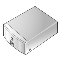
Exploded view of the packing configuration for the X-LA21 unit.

EXTERIOR SECTION DETAILS

Diagrams and parts list for the exterior components of the unit.

SCHEMATIC DIAGRAMS

OVERALL WIRING DIAGRAM

Block diagram showing the overall wiring connections of the unit.

AMPLIFIER, TRANSFORMER, PRIMARY ASSYS

Schematics for amplifier, transformer, and primary assemblies.

JACK, METER, LED, HP JACK ASSYS

Schematics for jack, power meter, LED, and HP jack assemblies.

PCB CONNECTION DIAGRAMS

AMP ASSY CONNECTION

PCB connection diagram for the amplifier assembly.

TRANSFORMER & PRIMARY ASSY CONNECTIONS

PCB connection diagrams for transformer and primary assemblies.

JACK ASSY CONNECTION

PCB connection diagram for the jack assembly.

METER, LED, HP JACK ASSY CONNECTIONS

PCB connection diagrams for meter, LED, and HP jack assemblies.

PCB PARTS LIST

Component Categories Listing

Parts list for components by type: semiconductors, resistors, capacitors, and others.

Assembly Parts Lists

Parts lists for specific assemblies like Primary, Power Meter, LED, and Jack.

GENERAL INFORMATION

DIAGNOSIS

Diagnostic procedures and information for the unit.

SINGLE OPERATION METHOD

Procedure for single operation testing using DC power supply.

DISASSEMBLY

Step-by-step guide for disassembling the unit.

PANEL FACILITIES AND SPECIFICATIONS

PANEL FACILITIES

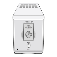
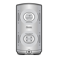
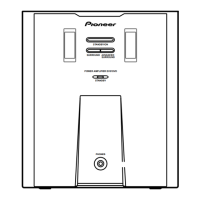
Description of the front panel controls and indicators.

SPECIFICATIONS

Technical specifications for power, dimensions, and weight.

Related product manuals