M-LA21
12
A
B
C
D
1
23
4
1234
E
E
E
Z2
Z1
WH601
Q617
P3
R670
D607
D609
D608
D610
CN603
EC633
IC605
W603
W607
W606
P2
W601
W602
W605
W604
EC622
EC623
R305
EC621
IC604
EC625
EC626
EC620
EC624
D612 D611
C618
C619
ORN
BLU
BLK
WHT
RED
WHT
YEL
ORN
RED
BRN
BLK
PWRCTL
CTLGND
MUTE
16VAC2
GND
16VAC1
ACVH2
ACVL2
ACGND
ACVL1
ACVH1
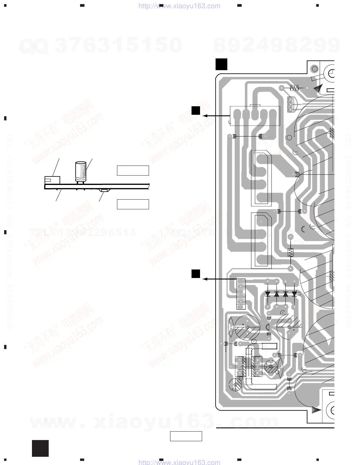
NOTE FOR PCB DIAGRAMS :
• Part numbers in PCB diagrams match those in the schematic
diagrams.
• The parts mounted on this PCB include all necessary parts for
several destinations.
For further information for respective destinations, be sure to
check with the schematic diagram.
• View point of PCB diagrams.
Capacitor
Connector
P.C.Board
Chip Part
SIDE A
SIDE B
Q617
AMP ASSY
A
WH1
B
CN1
B
SIDE A
A
4. PCB CONNECTION DIAGRAM
4.1 AMP ASSY
w
w
w
.
x
i
a
o
y
u
1
6
3
.
c
o
m
Q
Q
3
7
6
3
1
5
1
5
0
9
9
2
8
9
4
2
9
8
T
E
L
1
3
9
4
2
2
9
6
5
1
3
9
9
2
8
9
4
2
9
8
0
5
1
5
1
3
6
7
3
Q
Q
TEL 13942296513 QQ 376315150 892498299
TEL 13942296513 QQ 376315150 892498299
http://www.xiaoyu163.com
http://www.xiaoyu163.com