EasyManua.ls Logo

Pioneer PD-9700 Service Manual

Pioneer PD-9700
42 pages
To Next Page IconTo Next Page
Page #1 background imageLoading...
Page #1 background image
@)
PIONEER’
The
Art
of
Entertainment
e1vice
ORDER
NO.
ARP2297
COMPACT
DISC
PLAYER
PD-4
1
PD-9700
PD-41
AND
PD-9700
HAVE
THE
FOLLOWING
:
Model
:
Type
Power
Requirement
Remarks
PD-41
PD-9700
AC
220
V-230
V,
AC
230
V-240
V(switchable)*
AC
110
V,
120
V-127
V,
220
V,
240
V(switchable)
*
Change
the
connection
of
the
power
transformer's
primary
wiring.
@
This
manual
is
applicable
to
PD-41/KU,
PD-9700/KC,
HEM,
HB
and
SD
types.
@
Asto
the
PD-9700/KC,
HEM,
HB
and
SD
types,
refer
to
page
84.
©
Asto
the
disassembly
and
mechanism
descriptions,
refer
to
the
PD-41,
PD-9700
service
guide(ARP2318).
@
Ce
manuel
pour
le
service
comprend
les
explications
de
reglage
en
francais.
e
Este
manual
de
servicio
trata
del
metodo
ajuste
escrito
en
espanol.
CONTENTS
ele
SAFETY
INFORMATION
settais
detaeade
ine
renbedenee
av
eeesnalees
2
6.
REGLAGE
Perr
rrr
rer
reer
errr
errr
r
er
ee
eee
rere
rrr
errr
rere
e
red)
50
2.
EXPLODED
VIEWS
AND
PARTS
LIST
vrvvrrrrereeeeeterees
4
6.
AJUSTE
teccccecteteeeee
terete
enn
ee
etn
ee
enn
eeenee
settee
tea
eenes
66
BZ
PACKING
covcccceccecceceeeeteereeeeeseseseeseeseaeeeeeerenren
gees
11
T.IC
INFORMATION
cccccccetecrtecreseneer
eter
ettetaneeearecenas
82
4.
SCHEMATIC
DIAGRAM
AND
vvvsersrseceseeeeeesteseeees
12
8.
FOR
PD-9700/KC,
HEM,
HB
AND
SD
TYPES
84
P.C.BOARDS
CONNECTION
DIAGRAM
9,
PANEL
FACILITIES
<-1-::2ses0eseseeeseeseeessenenettttcee
86
5B.
P.C.B'SPARTS
LIST
cecceccceeeceecteeeecee
ee
eteeteueeeseenaes
32
10.
SPECIFICATIONS
cccceccerceteeceereeereca
reste
eseenneeen
rene
88.
6.
ADJUSTMENTS
crrreereeeeretretsrrtreteetee
eer
ereeeeaee
35
PIONEER
ELECTRONIC
CORPORATION
4-1,
Meguro
1-Chome,
Meguro-ku,
Tokyo
153,
Japan
PIONEER
ELECTRONICS
SERVICE
INC.
P.O.
Box
1760,
Long
Beach,
California
90801
U.S.A.
PIONEER
ELECTRONICS
OF
CANADA,
INC.
505
Cochrane
Drive,
Markham,
Ontario
L3R 8E3
Canada
PIONEER
ELECTRONIC
[EUROPE]
N.V.
Keetberglaan
1,
9120
Beveren,
Belgium
PIONEER
ELECTRONICS
AUSTRALIA
PTY. LTD.
178-184
Boundary
Road,
Braeside,
Victoria
3195,
Australia
TEL:
[03]
580-9911
©
PIONEER
ELECTRONIC
CORPORATION
1991
FI
JUNE
1991
Printed
in
Japan

Other manuals for Pioneer PD-9700

Question and Answer IconNeed help?

Do you have a question about the Pioneer PD-9700 and is the answer not in the manual?

Pioneer PD-9700 Specifications

General IconGeneral
BrandPioneer
ModelPD-9700
CategoryCD Player
LanguageEnglish

Summary

1. Safety Information

1. Safety Precautions

Safety checks for customer and technician, including leakage current.

2. Product Safety Notice

Importance of using specified replacement parts for safety and avoiding hazards.

Label Check

Additional Laser Caution

Important safety notes regarding laser operation and potential hazards.

2. Exploded Views and Parts List

2.1 Exterior

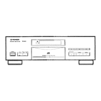
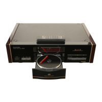
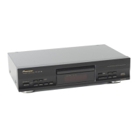
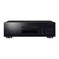
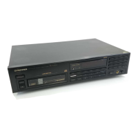
List and illustration of the player's external parts.

2.2 Mechanism Section

Exploded view of the player's internal mechanism components.

2.3 Remove the Tray Panel and the Tray Lens

Procedure for safely removing the tray panel and lens assembly.

2.4 Install the Tray Panel and the Tray Lens

Procedure for correctly installing the tray panel and lens assembly.

3. Packing

Terminal Voltages

4. Schematic Diagram and P.C.Boards Connection Diagram

Main Board Assembly

Schematic and connection diagram for the player's main board.

Primary Board Assembly

Schematic and connection diagram for the primary board.

4.2 Analog Board Assembly(PWM1490)

Schematic and connection diagram for the analog board.

4.3 Waveforms

Oscilloscope waveform examples for diagnostic testing.

5. P.C.B.'s Parts List

6. Adjustments

6-1. Adjustment Items/Verification Item and Order

List of all adjustment items and their verification steps.

6-2. Measuring Instruments and Tools

Required test equipment and tools for performing adjustments.

6-5. Test mode

Procedure for setting the player into test mode for service.

1. Focus Offset Adjustment

Procedure to set the DC offset for the focus error amplifier.

4. Pickup Radial/Tangential Tilt Adjustment

Adjusting pickup angle for optimal RF signal read-out.

6. Focus Servo Loop Gain Adjustment

Procedure to optimize the focus servo loop gain.

8. Focus Error Signal (Focus S Curve) Verification

Verifying pickup status by observing the focus error signal.

7. IC Information

Block Diagram

Functional block diagram of the SM5840CP digital filter IC.

Pin Assignment

Pin configuration details for the SM5840CP IC.

8. For PD-9700/KC, HEM, HB and SD Types

8.1 Contrast of Miscellaneous Parts

Comparison of miscellaneous parts across different model types.

9. Panel Facilities

Front Panel

Identification and layout of the player's front panel controls.

Remote Control Operations

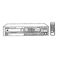
Guidelines for operating the player using the remote control unit.

10. Specifications

1. General

General characteristics like type, power, weight, and dimensions.

2. Audio Section

Technical details of the audio playback capabilities.

3. Output Terminal

Information on the player's audio and digital output connections.

4. Functions

Overview of basic operation and search functions.

5. Accessories

List of included accessories with the product.

Related product manuals