Do you have a question about the Pioneer PDP-508XDA and is the answer not in the manual?
Provides a quick reference for service visits, PD/SD diagnosis, and various settings.
Provides a flowchart for diagnosing failures in the video system.
Provides a flowchart for diagnosing failures in the audio system.
Details diagnosis for shutdown (SD) based on LED flashing frequency and error codes.
Provides an overview of the Service Factory Mode operations.
Lists Shutdown NG information for the MTB side, detailing causes and operations.
Details shutdown information of the MTB side, including SD Information No. and causes.
Presents the schematic diagram for Main Assy (1/20), focusing on the Board IF0 block.
Presents the schematic diagram for Main Assy (2/20), focusing on the Board IF1 block.
Provides the schematic diagram for Main Assy (3/20), detailing the Power 0 block.
Presents the schematic diagram for Main Assy (4/20), focusing on the Power 1 block.
Details the schematic diagram for Main Assy (5/20), focusing on the Power 2 block.
Shows the schematic diagram for Main Assy (6/20), focusing on the AV Switch block.
Presents the schematic diagram for Main Assy (7/20), focusing on the RGB Switch block.
Details the schematic diagram for Main Assy (8/20), focusing on the VDEC block.
Shows the schematic diagram for Main Assy (9/20), focusing on the ADC block.
Presents the schematic diagram for Main Assy (10/20), focusing on the HDMI Switch block.
Details the schematic diagram for Main Assy (11/20), focusing on the HDMI block.
Shows the schematic diagram for Main Assy (12/20), focusing on the Tuner block.
Presents the schematic diagram for Main Assy (13/20), focusing on the VBI Slicer block.
Details the schematic diagram for Main Assy (14/20), focusing on the USB block.
Shows the schematic diagram for Main Assy (15/20), focusing on the ARIA 0 block.
Presents the schematic diagram for Main Assy (16/20), focusing on the ARIA 1 block.
Details the schematic diagram for Main Assy (17/20), focusing on the ARIA Memory block.
Shows the schematic diagram for Main Assy (18/20), focusing on the IF UCOM block.
Presents the schematic diagram for Main Assy (19/20), focusing on the EMMA2 block.
Details the schematic diagram for Main Assy (20/20), focusing on the EMMA2 Memory block.
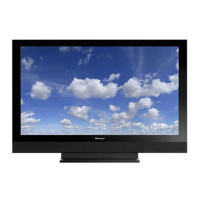
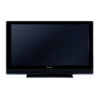
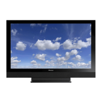
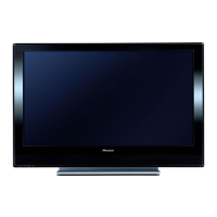
| Screen Size | 50 inches |
|---|---|
| Display Type | Plasma |
| HDMI Ports | 3 |
| Component Video Inputs | 2 |
| Aspect Ratio | 16:9 |
| Speakers | 2 x 10W |
| Contrast Ratio | 16000:1 |
| Viewing Angle | 160 degrees |
| Inputs | HDMI, Component, Composite, PC |



 Loading...