Do you have a question about the Pioneer PDP-427XD and is the answer not in the manual?
Crucial safety precautions for qualified service technicians, including warnings and notices.
Important notice regarding special safety characteristics of parts and potential hazards during repair.
Conformance to regulations and safety instructions during repairs, use of specified parts.
Procedure for transferring backup data for the Digital Video Assy using factory menu or RS-232C.
Visual chart outlining the recommended order for removing main parts and boards during disassembly.
Step-by-step guide for replacing the SCAN IC, including related component removal.
Block diagram showing the architecture of major functional blocks (part 1 of 2).
Block diagram showing the architecture of major functional blocks (part 2 of 2).
Block diagram of the power supply unit, detailing its circuits and outputs.
Block diagram showing the architecture of the 42 Digital Assy.
Diagram illustrating the signal flow between major components and assemblies.
Block diagram showing power supply distribution to the Main Assy.
Block diagram illustrating the audio processing and output paths.
Tables detailing voltage outputs for various assemblies like Digital, Main, and Tanshi.
Step-by-step guide for diagnosing and troubleshooting unit failures.
Flowchart for diagnosing potential failures in the power supply unit.
Flowchart for diagnosing failures within the digital assembly.
Flowchart for diagnosing failures within the X/Y Drive Assys.
Flowchart for diagnosing issues related to the main assembly.
Flowchart for diagnosing problems with the video signal processing.
Flowchart for diagnosing issues with the audio output and signals.
Flowchart for diagnosing failures in the entire unit.
Block diagram illustrating the power-down signal flow and related components.
Identifies failure symptoms, checkpoints, and causes for power-down events.
Block diagram illustrating the shutdown signal flow and related components.
Table correlating LED flashes, symptoms, checkpoints, and potential defective parts for shutdown.
Details adjustments needed after replacing specific assemblies or parts to ensure proper operation.
Identifies parts requiring whole-assembly replacement and explains reasons for adjustments.
Procedures for copying adjustment data from SENSOR to DIGITAL Assy using factory menu or RS-232C.
RS-232C commands for clearing logs like hour-meter, PD, SD, etc. after Assy replacement.
Factory menu steps for clearing logs like PD, SD, hour-meter, and MAX TEMP.
Adjusting Vofs and Vyprst voltages using RS-232C or Factory Menu based on panel label.
Clearing panel histories like hour-meter, SD, and PD after replacement using RS-232C or Factory Menu.
Covers transition charts, entry/exit, operation, remote codes, tables, and indications for service mode.
Comprehensive table detailing factory menu structure, variables, adjustment ranges, and remarks.
Details the structure and available functions within the factory menu (Information, Panel, Option, Initialize).
Displays shutdown NG information from MTB side, linking OSD indications to causes of shutdown.
Lists all functions within the Panel Factory menu, including information, operations, adjustments, and masks.
Outlines RS-232C commands, prepared tools, usage, and switching between SR+ and RS-232C modes.
Explains communication protocol, data format, command processing, reception confirmation, and error handling.
Defines single functional, adjustment, set, and state acquisition commands with their formats and examples.
Comprehensive list of RS-232C commands, their functions, modes, and remarks.
Acquires power-down (PD) logs, including status, hour meter, and subcategory information.
Acquires shutdown (SD) logs, including status, hour meter, and subcategory information.
Acquires MTB/MB side shutdown information, linking error codes to causes and operations.
Outlines processing steps for abnormalities like speaker short-circuit, power supply issues, fan/temp sensor, and antenna power.
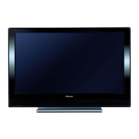
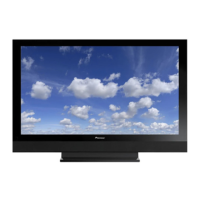
| Depth | 115 mm |
|---|---|
| Width | 1040 mm |
| Height | 679 mm |
| Weight | 29600 g |
| Pixel pitch | - mm |
| Aspect ratio | 16:9 |
| Product color | Black |
| LED indicators | Stand-by |
| Noise reduction | Yes |
| RMS rated power | 13 W |
| Display diagonal | 42 \ |
| Headphone outputs | 1 |
| Display brightness | 1100 cd/m² |
| Display resolution | 1024 x 768 pixels |
| Display technology | Plasma |
| Power requirements | AC 220 - 240 V, 50/60 Hz |
| SCART ports quantity | 3 |
| Contrast ratio (typical) | 3000:1 |
| Analog signal format system | PAL, SECAM |
| Power consumption (standby) | 0.7 W |
| Power consumption (typical) | 291 W |





 Loading...