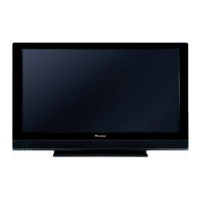
Do you have a question about the Pioneer PDP-507XA and is the answer not in the manual?
| 3D | - |
|---|---|
| Depth | 115 mm |
| Width | 1224 mm |
| Height | 717 mm |
| Weight | 34100 g |
| Tuner type | Analog |
| Pixel pitch | - mm |
| Smart modes | Energy saving |
| Aspect ratio | 16:9 |
| Product color | Black |
| LED indicators | Y, Power |
| Noise reduction | Yes |
| RMS rated power | 26 W |
| AC input voltage | 220 - 240 V |
| Display diagonal | 50 \ |
| Channels quantity | 99 channels |
| AC input frequency | 50 - 60 Hz |
| Display brightness | 1100 cd/m² |
| Display resolution | 1365 x 768 pixels |
| Display technology | Plasma |
| Number of speakers | 2 |
| Teletext standards | Top-text |
| SCART ports quantity | 3 |
| Supported video modes | 1080p |
| USB 2.0 ports quantity | 0 |
| Contrast ratio (typical) | 4000:1 |
| Annual energy consumption | - kWh |
| Display diagonal (metric) | 127 cm |
| Analog signal format system | NTSC, NTSC 3.58, NTSC 4.43, PAL, PAL 60, PAL BG, PAL DK, PAL I, SECAM, SECAM B/G, SECAM D/K, SECAM L |
| Power consumption (standby) | 0.3 W |
| Power consumption (typical) | 341 W |
| Sound enhancement technology | FOCUS, SRS, TruBass |
| Supported graphics resolutions | 1024 x 768 (XGA), 1280 x 768 (WXGA), 640 x 480 (VGA), 800 x 600 (SVGA) |
| Component video (YPbPr/YCbCr) in | 1 |
| On Screen Display (OSD) languages | CZE, DAN, DEU, DUT, ENG, ESP, FIN, FRE, GRE, ITA, NOR, POL, POR, RUS, SWE, TUR |
Essential safety precautions and warnings for technicians, including handling hazardous materials and electrical safety.
Block diagram showing the functional blocks and their interconnections within major assemblies (part 1/2).
Block diagram showing the functional blocks and their interconnections within major assemblies (part 2/2).
Diagram illustrating signal paths and interconnections between various input sources and processing blocks.
Block diagram showing the power distribution within the Main Assy, illustrating voltage lines and regulators.
Block diagram illustrating the power line distribution for the 50X and 50Y Drive Assys, including voltage generation.
Schematic diagram of the Power Supply Unit, detailing its primary and secondary circuits and voltage outputs.
Table listing voltage specifications for various drive assemblies and their respective connector pins.
Flowcharts for systematic troubleshooting of common failures across the entire unit.
Details on power-down signals, block diagrams, and analysis of failure symptoms leading to power-down.
Information on shutdown signals, block diagrams, and analysis of failure symptoms leading to shutdown.
Chart outlining the recommended order for removing and replacing main parts and PC boards.
Guidance on which assemblies require adjustment after repair or replacement.
Procedures for backing up and restoring panel adjustment data, essential after panel replacement.
Detailed steps for adjusting the panel after service replacement, focusing on Vofs voltage and white balance.
Procedures for adjusting time lag of control signals (SUS-B, SUS-D) after replacing drive assys.
Instructions for clearing various logs like power-on time, shutdown history, and temperature data.
Menu for panel adjustment, including information, works, power down, shutdown, and various mask/timing settings.
Comprehensive list of RS-232C commands with their functions, effective modes, and remarks.
Details on processing abnormal conditions such as speaker short-circuit, power supply issues, and fan/temperature sensor anomalies.


 Loading...