PDP-507XD
89
5678
56
7
8
C
D
F
A
B
E
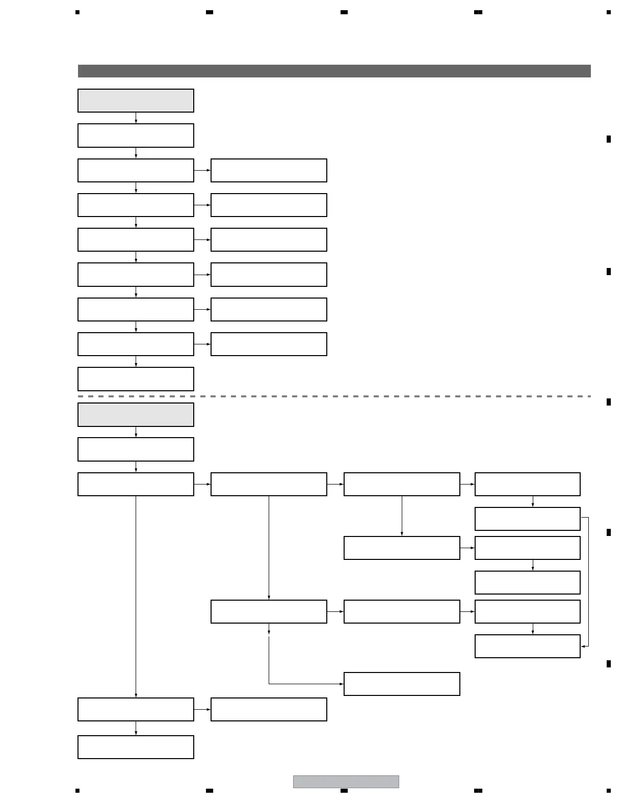
5.1.5 FLOWCHART OF FAILURE ANALYSIS FOR THE MAIN ASSY
Flowchart of Failure Analysis for The MAIN Assy
Failure in the RST IC (IC8302) output or its peripheral circuits
Yes
No
No
No
Yes
Replace the MAIN Assy.
Is the M1 connector securely
connected?
Is the cable that is connected to
the M1 connector broken?
The STB LED does not light although
STB 3.3 V power is supplied.
Securely connect the M1 connector.
No
Is the M5 connector securely
connected?
Securely connect the M5 connector.
Replace the cable (J207).
Yes
Yes
Is the cable that is connected to
the M5 connector broken?
Replace the cable (J113).
No
No
No
No
No
NG
NG
NG
The RELAY port does not work.
The power is not turned on.
Is voltage at REQ_IF (3.3 V) on
the MAIN Assy high?
Is the power (1.8 V, 3.3 V) supplied
to the main microcomputer?
Can the unit be turned on, using
the remote control unit?
Can the unit be turned on, using
the Power switch on the main unit?
Can the unit be turned on, using
the Power switch on the main unit?
Replace the cable that connects
the SIDE KEY and MAIN Assys.
Yes
Is resetting of the IF
microcomputer canceled?
Failure in the line between the IF microcomputer and M5 connector
If the voltage at Pin 129 (RST2 port) on the main
microcomputer is high, it is judged that the AC power
cord is not plugged in, and operation of the unit will stop there.
• Failure in the REC IC (IC4402) and PM SW (IC4407) outputs
• Does the voltage remain low even though it should be active?
• A shutdown, indicated by 9 flashes of LED, will be established in 20 seconds.
No
Replace the MAIN Assy.
Replace the MAIN Assy.
Yes
Is the voltage at Pin 1 of the M5
connector high?
No problem with the MAIN Assy.
Check the LED Assy.
No
Yes
Yes
Yes
Yes
NG
Replace the cable that connects
the LED IR and MAIN Assys.
Replace the cable that connects
the LED IR and MAIN Assys.
Replace the cable that connects
the SIDE KEY and MAIN Assys.
Replace the LED IR Assy.
NG
Replace the cable that connects
the SIDE KEY and MAIN Assys.
Replace the SIDE KEY Assy.
Replace the MAIN Assy.
Replace the MAIN Assy.
Replace the MAIN Assy.
NG
Yes
Failure analysis for the
MAIN Assy. ⇒ MA1
Failure analysis for the
MAIN Assy. ⇒ MA2
 Loading...