EasyManua.ls Logo

Pioneer RX-731 - User Manual

Pioneer RX-731
20 pages
Print Icon
To Next Page IconTo Next Page
Loading...
STEREO
DOUBLE
CASSETTE
DECK
RECEIVER
Gyevele:
0
RX-731(S)
7RX-730(S)
7
;
RX-1320(S)
STEREC
TURNTABLE
PLP
2OSRLY
Pie
22
PE
2252
The
model
PL-223Z
is
not
sold
in
the
U.S.A.
The
models
PL-203AZ
and
PL-223AZ
are
not
sold
in
Canada.
Thank
you
for
buying
this
Pioneer
product.
Please
read
through
these
operating
instructions
so
you
will
know
how
to
operate
your
mode!
properly.
After
you
have
fi-
nished
reading
the
instructions,
put
them
away
in
a
safe
place
for
future
reference.
in
some
countries
or
regions,
the
shape
of
the
power
plug
and
power
outlet
may
sometimes
differ
from
that
shown
in
the
explanatory
drawings.
However,
the
method
of
connecting
and
operating
the
unit
is
the
same.
WARNING:
To
prevent
FIRE
OR
SHOCK
HAZARD,
DO
NOT
EXPOSE
THIS
APPLIANCE
TO
RAIN
OR
MOISTURE.
IMPORTANT
NOTICE
[For
U.S.
and
Canadian
models]
The
serial
number
for
this
equipment
is
located
on
the
rear
panel.
Please
write
this
serial
number
on
your
enclosed
warranty
card
and
keep
it
in
a
secure
area.
This
is
for
your
security.
[For
Canadian
models]
CAUTION:
To
prevent
ELECTRIC
SHOCK
DO
NOT
USE
THIS
(POLARIZED)PLUG
WITH
AN
EXTENSION
CORD,
RECEPTACLE
OR
OTHER
OUTLET
UNLESS
THE
BLADES
CAN
BE
FULLY
INSERTED
TO
PREVENT
BLADE
EXPOSURE.
ATTENTION:
pour
pREvENIR
LES
CHOCS
ELECTRIQUES
NE
PAS
UTILISER
CETTE
FICHE
POLARISEE
AVEC
UN
PROLONGATEUR
UNE
PRISE
DE
COURANT
OU
UNE
AUTRE
SORTIE
DE
COURANT,
SAUF
SI
LES
LAMES
PEUVENT
ETRE
INSEREES
A
FOND
SANS
EN
LAISSER
AUCUNE
PARTIE
A
DECOUVERT.
TWO
VOLTAGE
SELECTOR
SWITCHES
Only
muiti-voltage
models
are
provided
with
these
switches.
U.
S.
and
Canadian
models
are
not
provided
with
these
switches.
Mains
voltages
in
Saudi
Arabia
are
127V
and
220V
only.
Never
use
this
model
with
110V
setting
in
Saudi
Arabia.
CHECKING
ACCESSORY
ITEMS
......0....0...0..0-.-.
BEFORE
OPERATION
............0....00000000
20008
ANTENNA
CONNECTIONS
...
CONNECTIONS
..........
REMOTE
CONTROL
UNIT
FACILITIES
-
:
TURNTABLE
FACILITIES...
2.2.2.2...
CONTENTS
PRELIMINARY
OPERATIONS........-..-------
20005
11
The
line
voltage
selector
switches
are
on
the
rear
panel.
Before
your
model
is
shipped
from
the
factory,
these
switches
are
set
to
the
power
requirements
of
the
destination.
Check
they
are
to
properly
before
plugging
the
power
cord
into
the
household
wail
socket.
If
the
voltage
is
not
properly
set
or
if
you
move
to
an
area
where
the
voltage
requirements
differ,
adjust
the
selector
switches
as
follows.
1.
Use
a
medium-size
screwdriver.
2.
First,
insert
a
screwdriver
into
the
groove
of
the
voltage
selector
at
the
top,
and
adjust
so
that
tip
of
the
groove
points
to
the
voltage
value
of
your
area.
3.
Next,
insert
the
screwdriver
into
the
groove
of
the
voltage
selector
at
the
bottom
and
adjust
until
the
voltage
is
the
same
as
at
the
top.
Both
switches
must
be
in
the
same
switch
setting.
rerawd
Lazo-24er)
CHANNEL
STEP
SWITCH
Only
muiti-voltage
models
are
provided
with
this
switch.
U.
S.
and
Canadian
models
are
not
provided
with
this
switch.
(This
switch
is
on
the
rear
panel.)
The
unit
has
been
factory
preset
to
the
channel
allocation
for
the
area
in
which
it
is
to
be
sold,
if
the
value
is
set
incorrectly,
frequency
display
may
stop
at
the
wrong
frequency,
or
sound
may
be
distorted,
resulting
in
an
inability
to
reproduce
reception
signals
at
their
proper
sound
quality.
For
this
reason,
be
sure
to
confirm
that
the
valueis
set
correctry
before
first
using
the
unit.
[100
kHz/10
kHz]
position:
Set
to
this
position
for
areas
with
FM
reception
step
of
100
kHz,
AM
10
kHz.
[50
kHz/9
kHz]
position:
Set
to
this
position
for
areas
with
FM
reception
step
of
50
kHz,
AM
9
kHz.
When
unsure
about
the
channel
allocation
for
your
area,
consult
your
dealer
for
correct
information.
CHANNEL
STEP
FM/AM
SETTING
THE
CLOCK
12
BASIC
OPERATIONS
12
CASSETTE
TAPE
RELAY
PLAYBACK
.- aS
satel
..
14
COPYING:
TAPES
«4
cot
cea
At
a
3
BS
path
td
ebay
3
14
MAINTENANCE...
0s
co
5
ce
ee
ee
bee
ee
16
TROUBLESHOOTING
......
17
SPECIFICATIONS
............---
:
ae
eae
HOW
TO
HANDLE
CASSETTE
TAPES.................
20
YQ
PIONEER’
The
future
of
sound
and
vision.
Question and Answer IconNeed help?

Do you have a question about the Pioneer RX-731 and is the answer not in the manual?

Summary

Important Notice

For U.S. and Canadian Models

Serial number location for security and warranty.

For Canadian Models

Caution regarding polarized plug use.

Voltage Selector Switches

Channel Step Switch

Safety Instructions

General Operating & Environmental Safety

Covers reading instructions, environment, location, and heat.

Power & Connection Safety

Covers power sources, cord protection, polarization, and cord caution.

Antenna & Appliance Safety

Covers antenna grounding, object entry, and condensation.

Service & Repair Precautions

Covers damage requiring service and user servicing limits.

Checking Accessory Items

Before Operation

Initial Turntable Set-Up

Step-by-step guide for setting up the turntable.

Antenna Connections

AM Antenna Setup

Instructions for connecting and positioning the AM loop antenna.

Antenna Connections

FM Antenna Setup

Instructions for connecting the FM T-type antenna.

External FM Antenna Installation

Guidance for connecting external FM antennas.

Connections

Connecting Input;Output Cords

How to connect audio input and output jacks.

Connecting Speaker Cords

Procedure for connecting speaker wires.

Connecting the Power Cord

Instructions for connecting the power cord to outlets.

Connections

Antenna Grounding

Recommendations for antenna grounding for protection.

Speaker Connections Note

Important notes on speaker impedance and connections.

Beat Cut Switch

Function of the beat cut switch for AM noise reduction.

AC Outlet Switched 200 W Max

Information on the switched AC outlet capacity and cautions.

Connections

Connecting VSP-333 Amplifier

How to connect the AV surround processor VSP-333.

Controlling Other Units Remotely

Operating other Pioneer equipment with the remote.

Multi-Room Remote Terminal

Connecting the multi-room remote control unit.

Panel Facilities

Tuner Section Controls

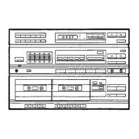
Overview of tuner controls, indicators, and switches.

Tuner Display Indicators

Indicators for tuner status, reception, and time.

Station Call & Memory

Switches for recalling and presetting stations.

Tuning & Band Selection

Switches for tuning stations and selecting FM/AM bands.

Time & Mono Settings

Switches for clock adjustment and FM mono reception.

Panel Facilities

Amplifier Section Controls

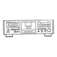
Front panel controls for power, speakers, volume, and functions.

Graphic Equalizer Controls

Controls for adjusting audio tone across five frequency bands.

Cassette Deck Controls

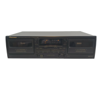
Controls for cassette deck operation, including Dolby and copying.

Remote Control Unit Facilities

Remote Control Range & Operation

Details on effective distance, angle, and environmental factors.

Installing Remote Control Batteries

Guide to inserting batteries correctly and safely.

Remote Control Buttons - Power & Volume

Controls for power on/off and adjusting volume.

Remote Control Buttons - Function & Surround

Selects input sources and surround sound modes.

Remote Control Buttons - Deck I & Deck II

Operates cassette deck playback, recording, and transport functions.

Remote Control Unit Facilities

Remote Control Buttons - Tuner & TV

Controls for tuning stations and changing TV channels.

Remote Control Buttons - CD & VDP

Operates CD player and VDP functions like playback and track search.

Turntable Facilities

Turntable Operation Switches

Switches for speed, arm elevation, and stopping playback.

Turntable Components

Identification of cartridge, tonearm, arm rest, and dust cover.

Turntable Installation Precaution

Avoid placing turntable near speakers to prevent vibration feedback.

Graphic Equalizer Controls

Preliminary Operations

Setting the Clock

Basic Operations

Turntable Record Play

Steps for playing vinyl records.

Listening to Broadcasts

Guide to tuning AM and FM radio stations.

Station Presetting & Tuning

Saving, recalling stations, and last station memory.

Basic Operations

Tape Playback

Instructions for playing cassette tapes in Deck I or II.

Auto Stop Mechanism

Automatic stop feature when tape reaches its end.

Recording Onto Cassette Tape

Guide to recording audio onto cassette tapes.

Basic Operations

Pausing and Restarting Recording

How to suspend and resume cassette tape recording.

Recording Q&A

Answers common questions about recording levels and tape types.

Recording with VSP-333

Connecting and recording with the VSP-333 processor.

Cassette Tape Relay Playback

Continuous playback between two decks.

Copying Tapes

Instructions for duplicating cassette tapes.

Copying Tapes

Mic Mixing

Mixing Know-How

Understanding how mixing combines audio sources.

Singing Along with Program Source

Using microphone with program sources for performance.

Maintenance

Cleaning the Head Section

Procedure for cleaning tape heads, capstan, and pinch roller.

Demagnetizing the Head

How to demagnetize the tape head to reduce noise.

Replacing the Stylus

Guide for safely removing and installing a new stylus.

Maintenance of External Surfaces

Instructions for cleaning the unit's exterior.

Troubleshooting

Troubleshooting Amplifier Section

Common issues and solutions for the amplifier.

Troubleshooting Cassette Deck Section

Common issues and solutions for tape decks.

Troubleshooting Tuner Section

Common issues and solutions for radio reception.

Troubleshooting

Troubleshooting Turntable

Common issues and solutions for the turntable.

Troubleshooting Remote Control Unit

Common issues and solutions for remote operation.

Specifications

Amplifier Section Specifications

Technical details for power output, inputs, and frequency response.

Miscellaneous Specifications

Power requirements, consumption, dimensions, and weight.

Turntable Specifications

Details on motor, drive, speed, tone arm, and cartridge.

Cassette Deck Specifications

Technical data for heads, motor, wow/flutter, and frequency response.

Tuner Specifications

FM and AM tuner frequency ranges and sensitivities.

Included Accessories

List of parts supplied with the unit.

How to Handle Cassette Tapes

Tips on Using Cassette Tapes

Advice on tape care, leader tape, and storage.

Accidental Erasure Prevention

Explanation and use of cassette tape tabs.

Cassette Tape Re-recording

Correct method for re-recording on tapes with broken tabs.

Incorrect Tape Application

Warnings about improper tape application methods.

Overview

This document describes the Pioneer Stereo Double Cassette Deck Receiver RX-731(S)/RX-730(S)/RX-1320(S) and Stereo Turntable PL-203AZ/PL-223AZ/PL-223Z. The PL-223Z model is not sold in the U.S.A., and PL-203AZ/PL-223AZ are not sold in Canada.

General Information

The receiver is designed for optimal sound quality and ease of use. It features a backup function that retains settings for several days even if the power cord is unplugged. The unit is controlled by an internal microprocessor, and if switches fail to respond, disconnecting and reconnecting the AC power after 5 seconds can reset it.

Amplifier Section

The amplifier delivers a continuous average power output of 125 watts per channel at 8 ohms from 20 Hz to 20,000 Hz, with no more than 0.09% total harmonic distortion.

Input Sensitivity/Impedance:

  • PHONO MM: 2.5 mV/47 kΩ
  • CD, VIDEO/AUX: 150 mV/47 kΩ

Frequency Response:

  • PHONO MM: 20 Hz to 20,000 Hz ±2 dB
  • CD, VIDEO/AUX: 20 Hz to 50,000 Hz ±3 dB

Signal-to-Noise Ratio (IHF, short circuited, A network):

  • PHONO MM: 72 dB
  • CD, VIDEO/AUX: 90 dB

Graphic Equalizer:

  • Frequency bands: 100 Hz, 330 Hz, 1 kHz, 3.3 kHz, 10 kHz
  • Adjustment range: ±8 dB

Controls and Indicators:

  • POWER STANDBY/ON switch: Turns the unit on or off. In standby, a minute flow of power maintains operational readiness, and the tuner display shows only the time.
  • MULTI-ROOM REMOTE indicator: Blinks when receiving signals from the Multi-room remote control unit.
  • PHONES jack: Standard plug-type jack for headphones.
  • SPEAKERS A/B switches: Selects speaker systems A or B. Both A and B can be on, but if only one speaker terminal is connected, only that selector should be on.
  • VOLUME control/indicator: Adjusts volume. Can be controlled by the remote.
  • BALANCE control: Adjusts the balance between left and right channels.
  • FUNCTION switches/indicators: Selects input sources (CD, PHONO, TUNER, TAPE, VIDEO/AUX).
  • GRAPHIC EQUALIZER controls: Five slide controls for adjusting specific frequency bands (100 Hz, 330 Hz, 1 kHz, 3.3 kHz, 10 kHz). These controls function during playback and recording, but not when copying tapes from Deck I to Deck II.
  • SPECTRUM ANALYZER display: Visualizes the audio spectrum.

FM Tuner Section

Frequency Range: 87.5 MHz to 108 MHz Usable Sensitivity: 14.2 dBf, IHF (1.4 µV/75 ohms) 50 dB Quieting Sensitivity: Mono: 20 dBf (2.7 µV/75 ohms); Stereo: 38 dBf (43.6 µV/75 ohms) Signal-to-Noise Ratio (IHF, 85 dBf Input): Mono: 70 dB; Stereo: 67 dB Stereo Separation: 43 dB (1 kHz) Frequency Response: 20 Hz to 15 kHz ±18 dB Antenna Input: 75 ohms unbalanced

Controls and Indicators:

  • Display section: Shows TUNED, STEREO, MONO, DECK II, SLEEP indicators, frequency, time, and recording time.
  • STATION CALL switches: Used to recall and preset up to 24 FM/AM stations.
  • Time switches: Used for clock adjustment.
  • FM MONO switch: Forces monaural reception for weak FM stereo signals. This setting is memorized with the station frequency.
  • MEMORY switch: Used to memorize stations.
  • BAND selector switch (FM/AM): Selects between FM and AM bands.
  • -, + switches: Used for tuning stations and adjusting the clock.

Usage Features:

  • Auto Tuning: Automatically searches for broadcasting stations.
  • Presetting Stations: Up to 24 FM/AM stations can be preset. The FM MONO setting is also recorded with the preset station frequency.
  • Last Station Memory: The last station received on either band is memorized even if power is turned off.

AM Tuner Section

Frequency Range: 530 kHz to 1,700 kHz Sensitivity (IHF, Loop antenna): 385 µV/m Antenna: Loop Antenna

Cassette Deck Section

Systems: 4 track, 2-channel stereo Heads: Recording/playback head x 1, Playback head x 1, Erasing head x 1 Motor: DC servo 2 speed motor x 2 Wow and Flutter: 0.09% (WRMS) Fast Winding Time: Approximately 95 seconds (C-60 tape)

Frequency Response (-20 dB recording):

  • Normal tape: 35 Hz to 14,000 Hz ± 6 dB
  • CrO2: 35 Hz to 15,000 Hz ± 6 dB

Signal-to-Noise Ratio:

  • Dolby NR OFF: 50 dB
  • Dolby B type NR ON: More than 10 dB (at 5 kHz)

Controls and Indicators:

  • Automatic tape selector function: Automatically detects tape type (NORMAL/CrO2/METAL for Deck I, NORMAL/CrO2 for Deck II).
  • DECK II COUNTER and reset switch: 3-digit display for tape travel on Deck II.
  • Indicators: Show tape direction, recording status (blinking for PAUSE, solid for recording, flashing for copying).
  • Deck I Operation switches: EJECT, PLAY (FWD/REV), STOP, FAST FORWARD, REWIND.
  • DOLBY NR switch:* Activates Dolby B noise reduction for playback of Dolby B recorded tapes.
  • COPY MODE switches: Selects normal speed or high-speed (double-speed) copying.
  • REV (REVERSE) MODE switch: Selects playback mode (Relay Play, Rec Play) and recording mode (Rec).
  • DECK II switches: REC (sets to recording standby), PAUSE (temporarily stops tape travel).
  • MIC jack (Multi-voltage model only): For microphone input.
  • MIC MIXING level control (Multi-voltage model only): Adjusts the balance between microphone and program source.

Usage Features:

  • Auto Stop Mechanism: Automatically stops when the end of tape is reached.
  • Auto Reverse Function: Uses rotary recording/playback heads for two-way recording and playback. Tape-end detection activates auto-reverse.
  • Tape Copying: Copies contents from Deck I to Deck II at normal or high speed. Graphic equalizer controls do not affect tape copying.
  • Relay Playback: Plays both tape sides, alternating between Deck I and Deck II for up to 6 cycles.
  • MIC Mixing: Combines microphone input with a program source.

Turntable [PL-203AZ/PL-223AZ/PL-223Z]

Motor, Platter:

  • Motor Type: DC servo motor
  • Drive Method: Belt drive
  • Speed: 33-1/3, 45 RPM
  • Speed Variation: 0.07% WRMS (JIS), ±0.10% WTD Peak (DIN)
  • Signal-to-Noise Ratio: 68 dB (DIN-B)
  • Platter: 295 mm dia., aluminum die-cast

Tonearm:

  • Type: Static balance straight pipe arm

Installed Cartridge:

  • Type: MM type
  • Replacement stylus: PN-240
  • Stylus: 0.6 mil diamond
  • Output voltage: 2.5 mV (1kHz, 5cm/s, Lat. peak)
  • Tracking Force: 1.5-2.5 g (optimum 2.0 g)
  • Frequency Response: 10 Hz to 30,000 Hz
  • Load Resistance: 47 kΩ
  • Cartridge Weight: 4 g

Controls and Features:

  • EP adaptor: For playing 45 rpm singles.
  • Platter spindle, Platter mat, Platter: Components for record playback.
  • SPEED switch: Selects 33-1/3 or 45 rpm.
  • ARM ELEVATION switch: Raises/lowers the tonearm for manual play, suspending play, or changing tracks.
  • STOP switch: Stops playback.
  • Cartridge, Tonearm, Arm rest: Essential tonearm components.
  • Dust cover (PL-223Z): Protects the turntable.

Usage Features:

  • Initial Turntable Set-up: Involves attaching the belt, placing the platter, and removing tonearm restraints.
  • Record Play: Manual operation for placing the tonearm and adjusting volume/tone.

Remote Control Unit

The remote control unit operates within approximately 7 meters and a 30-degree angle from the receiver's remote sensor window. Strong fluorescent light can affect performance. It uses two "AAA" dry cell batteries.

Keys:

  • POWER key: Turns the unit on/off.
  • VOLUME key: Adjusts sound volume. With SHIFT key, adjusts TV volume.
  • FUNCTION selector keys: Selects V/AUX, TUNER, PHONO. With SHIFT key, selects VCR1, VCR2, VDP.
  • SUR (surround) key: Selects surround mode.
  • DECK I operation keys: Forward/reverse playback, fast forward/rewind, stop.
  • DECK II operation keys: Forward/reverse playback, fast forward/rewind, stop, REC (recording standby), PAUSE.
  • TUNER/TV keys: STATION (+/- for station change), TUNING, BAND. With SHIFT key, CHANNEL (+/- for TV channel change), SLEEP (sets sleep timer).
  • CD/VDP operation keys: CD playback, DISC selection, stop, pause, track search, program. With SHIFT key, VDP playback, DISC SIDE, scan, pause, display on/off, DELAY TIME.

Connections

  • Line Voltage Selector Switches: Located on the rear panel, these must be set to the correct voltage for the region (e.g., 120V, 220V, 240V).
  • Channel Step Switch: Located on the rear panel (multi-voltage models only), sets FM reception step (100 kHz or 50 kHz) and AM step (10 kHz or 9 kHz).
  • Antenna Connections:
    • AM Loop Antenna: Supplied, connects to AM terminals. Should be placed away from metallic objects and radio frequency generating devices.
    • External AM Antenna: Vinyl-coated wire (5-6 meters) for improved reception.
    • FM T-type Antenna: Supplied, connects to FM terminals. Should be stretched out fully.
    • External FM Antenna: 300-ohm feeder wire or 75-ohm coaxial cable for weak signals or noisy reception. Coaxial cable is recommended for noise reduction.
  • Input/Output Cords: Connect turntable to TURNTABLE jacks, other stereo components to input/output jacks. White terminal for left, red for right.
  • Speaker Cords: Connect to SPEAKERS terminals. Speaker systems should have an impedance from 8Ω to 16Ω. Ensure secure connections and prevent shorting.
  • Power Cord: Plug into household electrical outlets. For U.S. and Canadian models, ensure proper polarity (wide blade into ground side slot).
  • Adaptor Terminals: For Australian and Multi-voltage models, for connecting components like dynamic expanders.
  • BEAT CUT switch: Minimizes beat noise during AM broadcast recording or tape copying while an AM broadcast is received.
  • AC OUTLET SWITCHED 200W MAX (U.S., Canadian, Multi-voltage models): Supplies power to connected equipment, turned on/off by the unit's POWER switch. Total power consumption should not exceed 200W. Avoid connecting high-power appliances.
  • Connecting AV Surround Processing Amplifier VSP-333: For U.S., Canadian, and multi-voltage models. Connects to the unit's AC OUTLET. Ensure power is OFF before connecting and set selecting switch before turning power ON.
  • Connecting Multi-Room Remote In Terminal: For the optional Multi-Room Remote control unit MR-100.

Maintenance

  • Cleaning the Head Section: Regularly clean heads, capstan, and pinch roller with a cleaning swab and fluid to prevent sound quality deterioration.
  • Demagnetizing the Head: Regularly demagnetize the head with a head demagnetizer (sold separately) to prevent noise and treble loss during recording/playback. Ensure the unit's POWER switch is in standby position.
  • Replacing the Stylus: Replace the stylus gently when worn or damaged (service life 800-1,000 hours). Use Pioneer "PN-240" replacement stylus.
  • Maintenance of External Surfaces: Wipe with a polishing cloth or soft dry cloth. For very dirty surfaces, use a soft cloth dipped in neutral cleanser diluted with water. Avoid furniture wax, benzine, insecticides, or other volatile liquids.

Troubleshooting

The manual provides a troubleshooting guide for common issues across the amplifier, cassette tape deck, tuner, and turntable sections, as well as for the remote control unit. It covers symptoms, causes, and remedies, such as:

  • No sound from speakers (volume down, incorrect speaker connections, VSP-333 switch setting).
  • Tape deck not working (tape loaded incorrectly).
  • Recording not possible (tape loaded in Deck I, dirty heads, erasure prevention tab removed).
  • High frequency sounds not reproduced (Dolby NR system on for non-Dolby tape, dirty heads).
  • Noise picked up during recording (TV on/too close, BEAT CUT switch setting).
  • AM/FM reception issues (antenna not connected, incorrect band selected, weak radio waves).
  • Turntable not working (drive belt not attached).
  • No sound from turntable (PHONO function not selected).
  • Static/scratching noise from turntable (dirty/warped/scratched record).
  • Remote control not working (dead battery, control cord not connected, fluorescent light interference).

Pioneer RX-731 Specifications

General IconGeneral
BrandPioneer
ModelRX-731
CategoryCassette Player
LanguageEnglish

Related product manuals