Do you have a question about the Pioneer CT-W205R and is the answer not in the manual?
Check leakage current to earth ground and all exposed metal parts for safety.
Electrical and mechanical parts have special safety characteristics identified by a symbol.
Lists external parts and packing details for various model types.
Procedures for entering and exiting the unit's test mode.
Overview of main test mode items, including SW check and speed check.
Procedures for door damping check, adjustment, and tape speed adjustment.
Prerequisites for electrical adjustments including head cleaning and warm-up.
Lists required jigs, measuring instruments like test tapes, oscilloscopes, and tools.
Procedure to adjust head azimuth for optimal playback.
Procedure to adjust playback level, critical for Dolby NR.
Procedure to adjust the bias oscillator frequency for recording.
Steps to adjust recording bias levels for different tape types.
Lists PCB assemblies for various models and their part numbers.
Details differences in construction for specific PCB assemblies.
Diagram showing the pin layout of the PD5351A U-COM IC.
Table detailing pin numbers, names, I/O, and functions for the PD5351A IC.
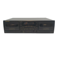
Describes the POWER (STANDBY/ON) switch for different model regions.
Covers DECK I Rewind Auto Play, Music Search, Dolby NR switch, eject, and operation buttons.
Covers DECK II Rewind Auto Play, Music Search, eject, and operation buttons.
Includes Function display, Synchro copy buttons, Reverse mode switch, and Rec Level control.
Covers heads, motor, wow/flutter, winding time, frequency response, and SNR.
Details input/output sensitivity, reference level, and harmonic distortion.
Lists subfunctions like auto reverse, music search, copy modes, and tape selector.
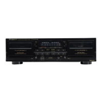
Covers miscellaneous specs like power, dimensions, weight, and accessories.
| power requirements for U.K. and Australian models | AC 220 - 230 volts, 50/60 Hz |
|---|---|
| power requirements for U.S. and Canadian models | AC 120 volts, 60 Hz |
| power consumption | 16W |
| wow and flutter | 0.09% (WRMS) |
|---|---|
| frequency response for TYPE IV (Metal) tape | 20 to 16, 500 Hz |
| frequency response for TYPE II (High/CrOz) tape | 20 to 16, 000 Hz |
| frequency response for TYPE I (Normal) tape | 20 to 16, 000 Hz |
| signal-to-noise ratio with Dolby NR OFF | More than 57 dB |
|---|---|
| noise reduction effect with Dolby B-type NR ON | More than 10 dB (at 5 kHz) |
| noise reduction effect with Dolby C-type NR ON | More than 19 dB (at 5 kHz) |
| input sensitivity for LINE (INPUT) | 100 mV (Input impedance 68 kΩ) |
|---|---|
| output reference level for LINE (OUTPUT) | 0.5 V (Output impedance 1.9 kΩ) |
| harmonic distortion | No more than 0.8% (at -4 dB: 160 nwb/m) |
| dimensions | 420 (W) x 125 (H) x 250 (D) mm |
|---|---|
| weight for U.K. and Australian models | 3.9 kg |
| weight for U.S. and Canadian models | 3.8 kg |