Do you have a question about the Pioneer CT-W404R and is the answer not in the manual?
General precautions for service technicians, including leakage current checks.
Notice regarding special safety characteristics of electrical components and the use of replacement parts.
Details about exterior parts, packing, and the associated parts list.
Detailed list of mechanism unit parts.
Instructions on how to enter the test mode.
Instructions on how to exit the test mode.
Details about tape speed adjustment and auto-stop check modes.
Test modes for CD Synchro and SW checks.
How to check and adjust door damping for proper operation.
Procedure for tape speed adjustment using test mode.
General conditions and prerequisites before performing electrical adjustments.
Overview of playback and recording adjustments to be performed.
Information on specific test tapes required for adjustments.
Procedure to adjust head azimuth for optimal playback quality.
Adjusting playback level using specific test tapes and settings.
Adjusting the bias oscillator frequency for recording.
Adjusting recording bias to achieve optimal distortion and level.
Procedure for setting recording levels with various tapes.
Verifying the accuracy of the level meters during operation.
Details of pin connections for the FL display.
Assignment of grid patterns for the FL display.
Connection details for the anodes of the FL display.
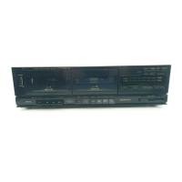
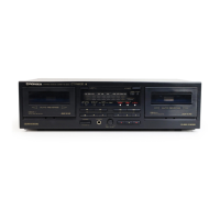
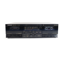
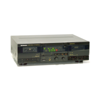
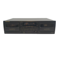
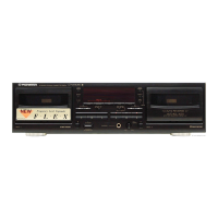
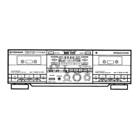
Description of various buttons, switches, and indicators on the front panel.
Functionality of Deck I play, stop, FF, rewind, eject, and counter controls.
Functionality of Deck II play, stop, FF, rewind, eject, and counter controls.
Buttons for FLEX, AUTO-NR, Synchro Copy, CD Sync, and Reverse modes.
Details on headphone jack and recording level control.
Technical specifications for the system, heads, and motors.
Measurement of wow and flutter for tape speed stability.
Specifications for signal-to-noise ratio with and without Dolby NR.
Harmonic distortion levels for different tape types.
Input sensitivity and impedance for LINE and Headphones.
Output reference level and impedance.
Power requirements, consumption, dimensions, weight, and accessories.
List of special functions and features of the device.
| Track System | 4-track, 2-channel stereo |
|---|---|
| Total Harmonic Distortion | 0.8% |
| Type | Double Cassette Deck |
| Heads | 2 x erase |
| Motor | DC Servo Motor |
| Power Supply | 50/60Hz |
| Inputs | 1 x RCA |
| Outputs | 1 x RCA |
| Input | Line In |
| Output | Line Out |