EasyManua.ls Logo

Pioneer S-FCRW220-S User Manual

Pioneer S-FCRW220-S
17 pages
To Next Page IconTo Next Page
Page #1 background imageLoading...
Page #1 background image
PIONEER CORPORATION 4-1, Meguro 1-Chome, Meguro-ku, Tokyo 153-8655, Japan
PIONEER ELECTRONICS SERVICE, INC. P.O. Box 1760, Long Beach, CA 90801-1760, U.S.A.
© PIONEER CORPORATION 2002
CONTENTS
1. SAFETY INFORMATION ............................................. 2
2. DISASSEMBLY ............................................................ 3
3. PACKING, EXPLODED VIEWS AND PARTS LIST ..... 3
4. SCHEMATIC AND PCB CONNECTION DIAGRAMS .. 6
5. PCB CONNECTION DIAGRAM ................................. 10
6. PCB PARTS LIST ...................................................... 13
7. ADJUSTMENT ........................................................... 15
8. PANEL FACILITIES.................................................... 16
9. SPECIFICATIONS ....................................................... 17
Service
Manual
ORDER NO.
PET02001
HOME THEATER LOUDSPEAKER SYSTEM
S-FCRW220
S-FCRW720
THIS MANUAL IS APPLICABLE TO THE FOLLOWING MODELS AND TYPES
CENTER
FRONT
SATELLITE
REAR
SATELLITE
POWER
REQUIREMENT
REMARKS
3 2 AC120VS-FCRW220-
K
MODEL
TYPE COMPONETS
3 2 AC120VS-FCRW220-
S
3 3 AC120VS-FCRW720-
S
SUBWOOFER
1
1
1
KCXCKUXC
w
w
w
.
x
i
a
o
y
u
1
6
3
.
c
o
m
Q
Q
3
7
6
3
1
5
1
5
0
9
9
2
8
9
4
2
9
8
T
E
L
1
3
9
4
2
2
9
6
5
1
3
9
9
2
8
9
4
2
9
8
0
5
1
5
1
3
6
7
3
Q
Q
TEL 13942296513 QQ 376315150 892498299
http://www.xiaoyu163.com
Question and Answer IconNeed help?

Do you have a question about the Pioneer S-FCRW220-S and is the answer not in the manual?
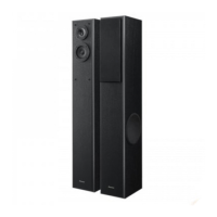
Pioneer S-FCRW220-S Specifications

General IconGeneral
Type2-Way Bass Reflex
Frequency Response50 Hz - 20 kHz
Sensitivity85 dB
ColorWhite
Impedance6 Ohm
Nominal Impedance6 ohm

Summary

Safety Information and Precautions

Product Safety Notice

Highlights critical safety characteristics of replacement parts for user safety.

Leakage Current Check Procedure

Procedure to measure and verify leakage current to earth ground.

Disassembly Procedures

Subwoofer Disassembly Guide

Detailed steps for dismantling the subwoofer unit.

Satellite Speaker Disassembly Guide

Instructions for dismantling the satellite speaker.

Packing, Views, and Parts Lists

3.1 Packing and Exploded Views

Exploded diagrams and parts list for packing.

3.2 Exterior Section Components

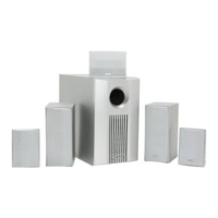
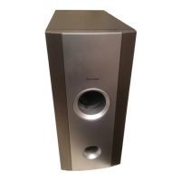
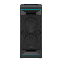
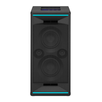
Lists exterior components for powered subwoofer and satellite speakers.

3.3 Power Amp Section Components

Lists internal components for the power amplifier section.

Block and Schematic Diagrams

4.1 Exterior Section Diagrams

Block diagram of the system's exterior section.

4.2 Amplifier and Operation Assemblies

Block diagrams for amplifier and operation assemblies.

PCB Connection Diagrams

PCB Parts List

Adjustment Procedures

7.1 Measuring Instruments Required

Lists required measuring devices for performing adjustments.

Gain Adjustment Guide

Instructions for adjusting the gain control (VR41).

Panel Facilities and Controls

Rear Section Overview

Overview of rear panel layout, terminals, and controls.

Power Indicator Light

Describes the function and color of the power indicator.

Subwoofer Level Control

Adjusts the subwoofer volume using the dedicated knob.

Subwoofer Input Terminal

Connects the receiver's subwoofer output.

Product Specifications

Front/Front Center Speaker Specifications

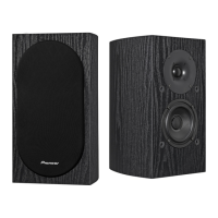
Technical specifications for front and front center speakers.

Powered Subwoofer Specifications

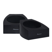
Technical specifications for the powered subwoofer unit.

Rear/Rear Center Speaker Specifications

Technical specifications for rear and rear center speakers.

Related product manuals