EasyManua.ls Logo

Pioneer SA-V210 Service Manual

Pioneer SA-V210
23 pages
To Next Page IconTo Next Page
Page #1 background imageLoading...
Page #1 background image
0)
PIONEER’
The
future
of
sound
and
vision.
Service
ALEVE
STEREO
MIXING
AMPLIFIER
SA-Ve2!
¢
This
manual
is
applicable
to
the
SA-V210/SE
type.
ORDER
NO.
ARP1902
CONTENTS
1.
SPECIFICATIONS
-cccecececeesecesescececcecessesaeecnes
2
2.
EXPLODED
VIEWS
AND
PARTS
LIST
--+------+++
3
3.
SCHEMATIC
DIAGRAM
cctcccccecctereceeceecsceeeens
7
4.
P.C.BOARDS
CONNECTION
DIAGRAM-:-------
13
5.
ELECTRICAL
PARTS
LIST
-rccceecerececeectceseeenes
25
6.
ADJUSTMENTS
«occcececccececceerecceeeteeeesceneenes
30
Bi
REGLAGE
ss
seco
owecditeet
eosdieseettecciessaunetovesces
31
6.
ASUSTE
<2
orc
cece
cece
cece
cence
cece
ence
neces
ns
eseeeanneeeas
32
7.
PANEL
FACILITIES
«--ccceeeceee
eee
ceeteeeesseeeeenees
33
PIONEER
ELECTRONIC
CORPORATION
=
4-1,
Meguro
1-Chome,
Meguro-ku,
Tokyo
153,
Japan
PIONEER
ELECTRONICS
SERVICE
INC.
P.O.
Box
1760,
Long
Beach,
California
90801
U.S.A.
PIONEER
ELECTRONICS
OF
CANADA,
INC.
505
Cochrane
Drive,
Markham,
Ontario
L3R
8E3
Canada
PIONEER
ELECTRONIC
[EUROPE]
N.V.
Keetberglaan
1,
2740
Beveren,
Belgium
PIONEER
ELECTRONICS
AUSTRALIA
PTY.
LTD.
178-184
Boundary
Road,
Braeside,
Victoria
3195,
Australia
TEL:
[03]
580-9911
©
PIONEER
ELECTRONIC
CORPORATION
1989
YA
Dec
1989
Printed
in
Japan.

Other manuals for Pioneer SA-V210

Question and Answer IconNeed help?

Do you have a question about the Pioneer SA-V210 and is the answer not in the manual?

Pioneer SA-V210 Specifications

General IconGeneral
Input Sensitivity (Phono)2.5mV
Input Sensitivity (Line)150mV
Signal-to-Noise Ratio (Line)85dB
OutputHeadphones
Speaker Load Impedance8Ω to 16Ω
Total Harmonic Distortion0.05%

Summary

1. SPECIFICATIONS

AMPLIFIER SECTION

Details technical specifications for the amplifier, including power output and input sensitivity.

Tone Control and Power Details

Specifies tone control ranges, power requirements, and unit dimensions.

2. EXPLODED VIEWS AND PARTS LIST

Component Identification and Notes

Provides general notes on parts replacement and a detailed list of components with part numbers.

3. SCHEMATIC DIAGRAM

Main Circuit Schematics

Presents detailed circuit diagrams for the unit's various assemblies.

4. P.C.BOARDS CONNECTION DIAGRAM

PCB Interconnection Diagrams

Illustrates how different printed circuit board assemblies are interconnected.

5. ELECTRICAL PARTS LIST

Component Breakdown by Assembly

Lists electrical parts categorized by assembly, such as Transistor, Rear, and Switch assemblies.

General Component Categories

Details semiconductors, resistors, capacitors, coils, relays, and switches used in the unit.

6. ADJUSTMENTS

Key Controller Gain Adjustment Procedure

Provides a step-by-step guide for adjusting the gain of the key controller.

7. PANEL FACILITIES

Rear Panel Layout and Controls

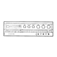
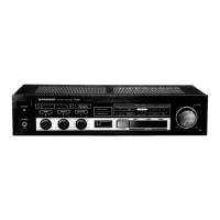
Illustrates the layout and identifies the controls and connectors on the rear panel.

Front Panel Layout and Controls

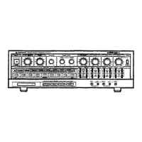
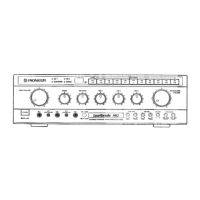
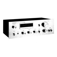
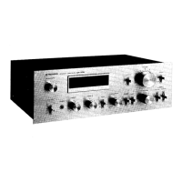
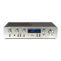
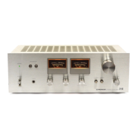
Illustrates the layout and identifies the controls and indicators on the front panel.

Related product manuals