Do you have a question about the Pioneer SA-708 and is the answer not in the manual?
Details of ICs, FETs, and transistors used in the unit.
Technical specifications for amplifier power output and distortion levels.
Specifications for bass, treble, subsonic filter, and loudness compensation.
Noise levels and input sensitivity for various audio sources.
Voltage, power consumption, dimensions, and weight of the unit.
Controls for power supply, speaker selection, and audio muting.
Volume control, headphone jack, and function/power indicators.
Controls for tone adjustment, channel balance, and input source selection.
Switches for subsonic filter, stereo/mono mode, and tape operations.
Description of the phono input stage and RFI filtering.
Explanation of the bass and treble control circuitry.
Detailed description of the amplifier's power stages and performance.
Explanation of indicator operation and protection mechanisms.
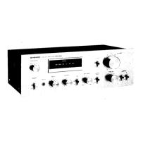
Identification of parts on the front panel assembly.
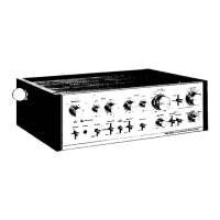
Identification of components after front panel removal.
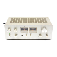
Identification of components visible from the top view.
Identification of connectors and ports on the rear panel.
Procedure for adjusting idle current for optimal performance.
Procedure for calibrating the output power indicator.
List of miscellaneous components for modifications.
Detailed circuit diagrams for the amplifier.
Diagram showing connections between circuit boards.
Comprehensive list of parts for various assemblies.
| Input Sensitivity | 2.5mV (MM), 150mV (line) |
|---|---|
| Power Output | 50 watts per channel into 8Ω (stereo) |
| Frequency Response | 5Hz to 100kHz |
| Dimensions | 420 x 150 x 369mm |
| Speaker Load Impedance | 4Ω to 16Ω |
| Total Harmonic Distortion | 0.05% (20Hz-20kHz, 50 watts) |