Do you have a question about the Pioneer SA-7800 and is the answer not in the manual?
Details on Bass, Treble, Subsonic Filter, Loudness, Hum, and Noise.
Operation of the power switch and the power indicator lamp.
Controls for enhancing low frequencies at low volumes and overall sound level.
Adjusts low and high frequency audio levels.
Covers RF interference filter and the equalizer amplifier stage.
Details the 3-stage tone amplifier circuit.
Explains the power amplifier circuitry, including differential and pre-driver stages.
Describes the circuit preventing amplifier instability during overdriving.
Further explanation of the NSA circuit's operation to prevent power stage cut-off.
Describes the fluorescent indicator tubes and their drive circuits.
Details the circuit protecting speakers from overload and DC voltage.
Explains the muting function during power transitions.
Describes the circuit that detects and responds to overload conditions.
Explains the detection of DC voltage in the output and its effect.
Procedure for adjusting idle current in the power amplifier.
Steps to adjust the output power indicator levels.
Instructions for removing the wooden case.
Steps for detaching the bottom plate.
Instructions for removing the front panel components.
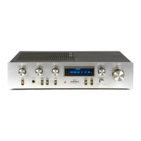
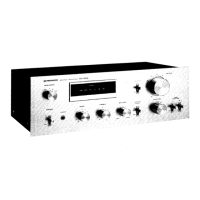
Identifies parts on the front panel of the unit.
Detailed breakdown of unit components and their assembly.
Illustrates component assembly including the wooden case.
| Power Output | 65 watts per channel into 8Ω (stereo) |
|---|---|
| Frequency Response | 5Hz to 100kHz |
| Input Sensitivity | 2.5mV (MM), 150mV (line) |
| Speaker Load Impedance | 4Ω to 16Ω |
| Dimensions | 420 x 150 x 376mm |
| Semiconductors | 4 x IC |
| Channel Separation | 60dB (line) |