Do you have a question about the Pioneer SA-8100 and is the answer not in the manual?
Uses differential amplifier circuits for stable DC potential balance and reduced switching noise.
Direct-coupled, constant-current circuit ensures stable transistor characteristics and minimum distortion.
Uses selected components for precise adherence to the RIAA curve, ensuring accurate sound reproduction.
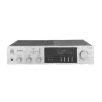
Four tone controls (bass and treble) allow flexible adjustment of frequency response for optimal sound.
Allows pre-setting maximum volume to -15dB or -30dB for finer adjustments with sensitive speakers.
Protects speakers and transistors via DC potential control, power limiting, and an electronic protection circuit.
Features preset level controls, tape I/O, filters, and dual speaker drive for enhanced system flexibility.
Connect speakers to A or B terminals, ensuring correct polarity (+/-) for optimal sound and protection.
Procedure for changing the unit's line voltage setting and checking/replacing the fuse.
Instructions for replacing a blown fuse, referring to Fig. 5 for fuse type and location.
Pre-operation checklist including volume, level set, muting, speaker, mode, and tone controls.
| Total Harmonic Distortion | 0.1% |
|---|---|
| Damping Factor | 40 |
| Input Sensitivity | 2.5mV (MM), 150mV (line) |
| Signal to Noise Ratio | 90dB (line) |
| Semiconductors | 2 x FET |